
Surface acoustic wave device and surface acoustic wave filter

a surface acoustic wave and filter technology, applied in the direction of impedence networks, electrical devices, etc., can solve the problems of affecting the operation of the device, the characteristics of the surface acoustic wave resonator are likely to be deteriorated, and the electrode fingers are likely to be damaged or destroyed, so as to improve the ability of electric power handling and reduce the effect of resonator size or prevent the increas

Active Publication Date: 2019-10-03
MURATA MFG CO LTD
View PDF1 Cites 2 Cited by
  • Summary
  • Abstract
  • Description
  • Claims
  • Application Information

AI Technical Summary

Benefits of technology

The present invention aims to improve the performance of surface acoustic wave devices by reducing the size of the resonator and increasing its electric power handling capability. These improvements enable better electric power handling and prevent excessive increase in the size of the device. Overall, this invention provides surface acoustic wave devices with better performance and more efficient energy handling.

Problems solved by technology

Providing small IDT electrodes and high power causes electrical and mechanical stresses due to the high power and a piezoelectric effect to occur on resonators.
The characteristics of surface acoustic wave resonators are thus likely to be deteriorated, or electrode fingers are likely to be damaged or destroyed.
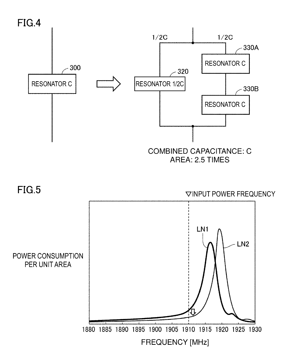
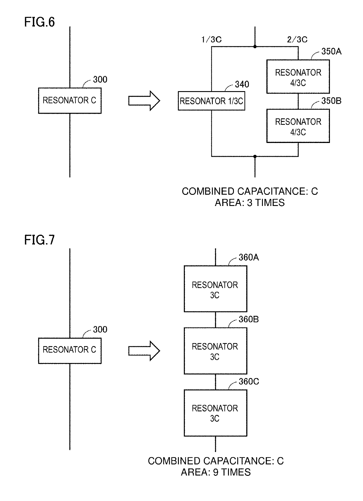
For example, in the case of two-stage division, the area of the IDT electrodes increases by four times. In the case of three-stage division, the area of the IDT electrodes increases by nine times. This is disadvantageous from the viewpoint of filter downsizing.

Method used


Image

  • Surface acoustic wave device and surface acoustic wave filter
  • Surface acoustic wave device and surface acoustic wave filter
  • Surface acoustic wave device and surface acoustic wave filter

Examples


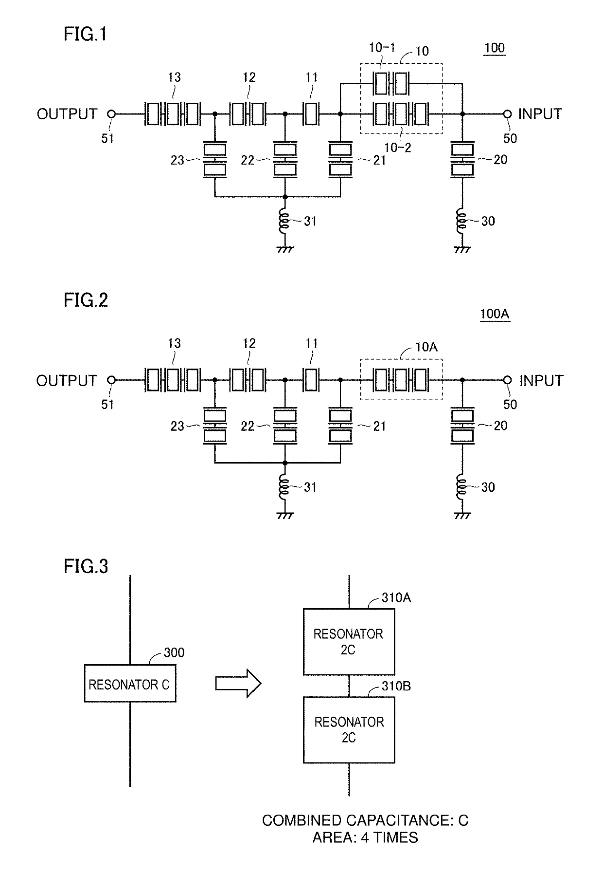
Embodiment Construction

[0031]Hereinafter, preferred embodiments of the present invention will be described in detail with reference to the drawings. Note that the same or equivalent components in the figures are denoted by the same reference numerals, and description thereof is not repeated.

[0032]FIG. 1 is a circuit diagram illustrating an example of a surface acoustic wave filter 100 according to a preferred embodiment of the present invention. With reference to FIG. 1, the surface acoustic wave filter 100 has a ladder configuration including series arm resonance sections 10 to 13 and parallel arm resonance sections 20 to 23. The series arm resonance sections 10 to 13 are connected in series in a series arm provided between an input terminal 50 and an output terminal 51. The parallel arm resonance sections 20 to 23 are each provided in a parallel arm connected between the series arm and a ground potential. Each resonance section includes one or more surface acoustic wave devices, and each surface acousti...


PUM


Abstract

A surface acoustic wave filter includes series and parallel arm resonance sections. The series arm resonance section is in a series arm. The parallel arm resonance section is in a parallel arm. The series arm resonance section includes one or more surface acoustic wave devices. Each surface acoustic wave device includes a first resonator group and a second resonator group. The first and second resonator groups are connected in parallel and include surface acoustic wave resonators. The first resonator group includes at least one surface acoustic wave resonator. The second resonator group includes a greater number of surface acoustic wave resonators than the at least one surface acoustic wave resonator in the first resonator group. The resonant frequency of the surface acoustic wave resonator in the first resonator group is higher than the resonant frequency of the surface acoustic wave resonators in the second resonator group.

Description

CROSS REFERENCE TO RELATED APPLICATIONS[0001]This application claims the benefit of priority to Japanese Patent Application No. 2016-251332 filed on Dec. 26, 2016 and is a Continuation Application of PCT Application No. PCT / JP2017 / 045759 filed on Dec. 20, 2017. The entire contents of each application are hereby incorporated herein by reference.BACKGROUND OF THE INVENTION1. Field of the Invention[0002]The present invention relates to a surface acoustic wave device and, more specifically, to technology for improving the electric power handling capability of a surface acoustic wave device used for a ladder surface acoustic wave filter including series arm resonators and parallel resonators.2. Description of the Related Art[0003]A surface acoustic wave filter in a ladder type configuration is known. In the ladder type configuration, a plurality of surface acoustic wave (SAW) resonators are alternately disposed in series arms and parallel arms. The surface acoustic wave resonator has a s...

Claims


Application Information

Patent Timeline
Patent Type & Authority Applications(United States)
IPC IPC(8): H03H9/02H03H9/64H03H9/145
CPCH03H9/02574H03H9/643H03H9/6433H03H9/14538H03H9/6483H03H9/6426H03H9/02929H03H9/02834H03H9/64
Inventor OTA, NORIYOSHI
Owner MURATA MFG CO LTD
Learn More