[0011]Various embodiments of the present invention will now be described in detail with reference to the accompanying drawings. In the following description, specific details such as detailed configuration and components are merely provided to assist the overall understanding of these embodiments of the present invention. Therefore, it should be apparent to those skilled in the art that various changes and modifications of the embodiments described herein can be made without departing from the scope and spirit of the present invention. In addition, descriptions of well-known functions and constructions are omitted for clarity and conciseness.
[0012]Embodiments of the invention are described herein with reference to illustrations of idealized embodiments (and intermediate structures) of the invention. As such, variations from the shapes of the illustrations as a result, for example, of manufacturing techniques and/or tolerances, are to be expected. Thus, embodiments of the invention should not be construed as limited to the particular shapes of regions illustrated herein but are to include deviations in shapes that result, for example, from manufacturing.
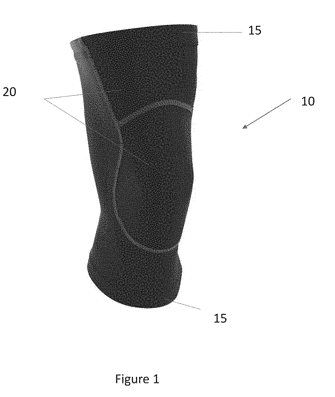
[0013]FIG. 1 illustrates an exemplary support brace 10. The support brace 10 may be configured to be placed on a user's body to increase stability of, and provide compression to, one or more body parts. The support brace 10 may comprise one or more compression or stability device, such as but not limited to, compression materials, rods, stiffening members, braces, or the like. In exemplary embodiments, the support brace 10 may be adjustable or sized to fit various size users. For example, without limitation, the support brace 10 may be a wrap configured to be wrapped around a joint. As a further example, again without limitation, the support brace 10 may be a section of material configured to be secured to a body part, such as by use of an adhesive. In still another example, again without limitation, the support brace 10 may be configured to be secured to one or more body parts such as but not limited to, a user's knee, elbow, wrist, back, neck, or ankle. In some exemplary embodiments, the support brace is a sleeve.
[0014]The support brace 10 may comprise various attachment and adjustment devices configured to secure the support brace 10 to the user's respective body part. Such attachment and adjustment devices may include, without limitation, the use of stretchable sections 20, stretchable bands 15, straps, fasteners, buckles, laces, adhesives, cut outs, or the like. The support brace 10, including but not limited to the stretchable sections 20 and the stretchable bands 15, may be comprised of a two-, three-, or four-way stretchable material such as but not limited to, latex, elastic, neoprene, or the like. All or some of the support brace 10, including but not limited to the stretchable sections 20 and the stretchable bands 15, may be coated with an anti-slip material to prevent the support brace 10 from slipping during wear. The support brace 10 may further comprise padded sections. The support brace 10 may further comprise one or more supporting elements such as, but not limited to, a stiffening member, a rod, straps, compression devices, and the like.
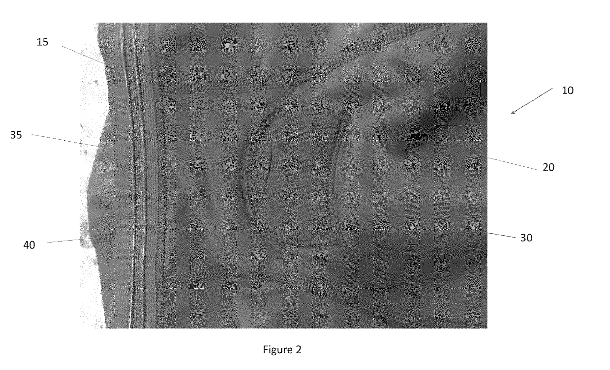
[0015]FIG. 2 illustrates an interior view of an exemplary support brace 10. The support braces 10 may comprise an attachment device 30 configured to accommodate one or more pain relief or rehabilitation assistance devices 45. The attachment device 30 may secure the one or more pain relief or rehabilitation assistance devices 45 to the support brace 10 around a particular location on the user's body. For example, without limitation, the attachment device 30 may be a pocket. The use of one or more pockets is contemplated. The pocket may be sewn, welded, adhered, fastened, or otherwise bonded to the support brace 10. In exemplary embodiments, the pocket material is sewn so such that the top to bottom will be in the weft direction, thereby allowing more longitudinal stretch. In other exemplary embodiments, the remaining portions of the pocket and support brace 10 may be sewn in the warp direction, thereby allowing more latitudinal stretch. Regardless, the pocket may comprise one or more slits 35 or other apertures located on or around the pocket and configured to permit the one or more pain relief or rehabilitation assistance devices 45 to be selectively inserted into and removed from the pocket. The pocket may further comprise an elastomeric pad 40 configured to provide a cushion between the pain relief or rehabilitation assistance device 45 located in the pocket 30 and the user's skin. In exemplary embodiments, the pain relief or rehabilitation assistance device 45 may be an electromagnetic pulse therapy device, such as but is not limited to, the ActiPatch® device manufactured by BioElectroincs (http://www.bielcorp.com/products/actipatch/).
[0016]In an exemplary embodiment, the support brace 10 is a knee brace configured to be worn about the user's knee. The support brace 10 may be comprised of one or more stretchable sections 20 and comprise one or more stretchable bands 15 configured to secure the support brace 10 to the user's knee. The support brace 10 may further comprise an attachment device 30 in the form of a pocket, which may be sized and configured to accommodate a pain relief or rehabilitation assistance device 45 including the Acti Patch® device. For example, without limitation, the attachment device 30 may be located so as to provide electromagnetic therapy to the upper center of the knee so as to relieve common knee pain.
[0017]Any number, location, size, shape, orientations, or type of attachment devices 30 are contemplated.
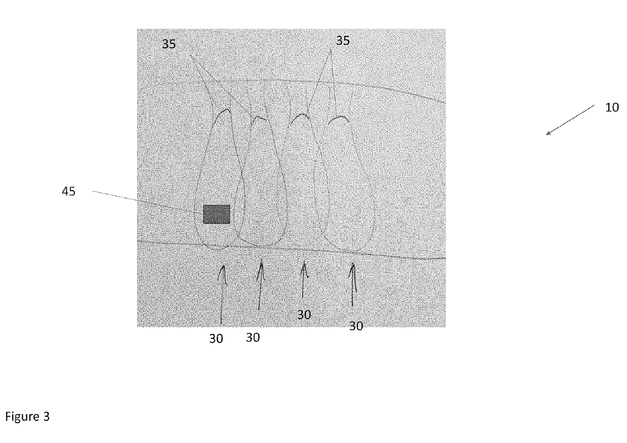
[0018]As illustrated in FIG. 3 multiple attachment devices 30, such as but not limited to pockets, may be located around an area for treatment. In this way, for example, without limitation, the pain relief or rehabilitation assistance device 45 may be moved from one attachment device 30 to another to best locate the pain relief or rehabilitation assistance device 45. As another example, without limitation, multiple pain relief or rehabilitation assistance device 45 may be used. The attachment devices 30 may be aligned in a substantially linear fashion along the support brace 10, though such is not required. The attachment devices 30 may be positioned along an area of common injury for the body part. For example, without limitation, the attachment device 30 may be located within the support brace 10 to align with the anterior cruciate ligament (ACL), the posterior cruciate ligament (PCL), the medial collateral ligament (MLC), the lateral collateral ligament (LCL) the lateral meniscus, or the medial meniscus of the knee.
[0019]In one exemplary embodiment, without limitation, multiple attachment device 30 may be located along a knee brace to permit positioning of the pain relief or rehabilitation assistance device 45 where the user is experiencing pain. In another exemplary embodiment, without limitation, the support brace 10 may be configured to be placed along the user's back and the attachment device 30 may be located in spaced intervals vertically to correspond with locations along the user's spinal column such that the pain relief or rehabilitation assistance device 45 may be positioned at various locations along the user's spine.
[0020]Any embodiment of the present invention may include any of the optional or preferred features of the other embodiments of the present invention. The exemplary embodiments herein disclosed are not intended to be exhaustive or to unnecessarily limit the scope of the invention. The exemplary embodiments were chosen and described in order to explain the principles of the present invention so that others skilled in the art may practice the invention. Having shown and described exemplary embodiments of the present invention, those skilled in the art will realize that many variations and modifications may be made to the described invention. Many of those variations and modifications will provide the same result and fall within the spirit of the claimed invention. It is the intention, therefore, to limit the invention only as indicated by the scope of the claims.