Check patentability & draft patents in minutes with Patsnap Eureka AI!

Method for increasing the injection speed of a plastic injection device

a technology of injection device and injection speed, which is applied in the field of modifying an injection device, can solve the problems of large investment of money and labor in the construction of new machines, and achieve the effects of increasing productivity, simple and quick manner, and increasing output pressur

Active Publication Date: 2019-10-10
SIPA SOCIETA INDUSTRIALIZZAZIONE PROGETTAZIONE E AUTOMAZIONE SPA
View PDF0 Cites 0 Cited by
  • Summary
  • Abstract
  • Description
  • Claims
  • Application Information

AI Technical Summary

Benefits of technology

The invention provides a method for increasing the speed of injecting melted plastic by modifying existing injectors in a simple and affordable manner. A modified injector can provide greater output pressure and productivity, without the need for expensive or complex new machines or significant changes to existing machines. The method involves reducing the inner diameter of the injector without increasing its height, which results in an increased output pressure of the melted plastic. This increased output pressure can be utilized to increase preform production without sacrificing the amount of melted plastic available for injection.

Problems solved by technology

However, since very complex machines are involved which comprise a large amount of cylinder-piston systems and respective injectors for simultaneously producing the greatest number of preforms possible, the construction of new machines requires large investments of money and labor.

Method used


Image

  • Method for increasing the injection speed of a plastic injection device
  • Method for increasing the injection speed of a plastic injection device
  • Method for increasing the injection speed of a plastic injection device

Examples


Embodiment Construction

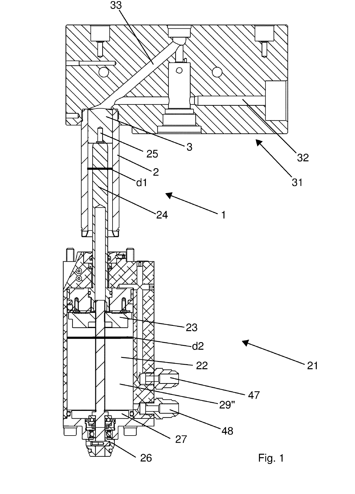
[0040]FIG. 1 shows an injection device provided with an injector 1, with a pneumatic cylinder 21 and with a chamber, also known as a hot chamber 31. Injector 1 can be modified by means of the method of the present invention.

[0041]FIG. 2 shows the injection device of the invention, which has a modified injector 11 with respect to injector 1 in FIG. 1. For the sole purpose of better understanding the invention, other components with which the injection device may be provided have been omitted from FIGS. 1 and 2.

[0042]The injector is also known as a dosing injector or cylinder, and serves to inject melted plastic for the production of plastic objects, for example for the production of bottle preforms (not shown) made of thermoplastic material such as PET.

[0043]Injector 1 comprises a hollow tubular casing 2, which substantially is a hollow cylindrical body, which has an inner diameter d1. The inner diameter d1 defines an inner area A1=π (d1 / 2)2. Such an inner area A1 is the area of a cr...


PUM

PropertyMeasurementUnit
inner diameter d3aaaaaaaaaa

Abstract

A method for increasing the injection speed of a melted plastic injection device for injecting said melted plastic into a molding cavity (51), said injection device comprising: —a first cylinder (1) provided with a tubular casing (2) defining a first inner diameter d1, and a first piston (3) slidable inside said tubular casing (2), adapted to be loaded with melted plastic and to inject said melted plastic toward the molding cavity (51); a second cylinder (21) constrained to the first cylinder (1) and provided with a second piston (23) which rod (24) is connected to the first piston (3) and is adapted to actuate said first cylinder (1) during an injection operation; the method comprising the steps of: —releasing second cylinder (21) and first cylinder (1) by extracting the first piston (3) from the tubular casing (2); —coaxially inserting a tubular body (12), defining a second inner diameter d3 which is smaller than the first inner diameter d1, into the tubular casing (2); —disconnecting the first piston (3) from the rod (24); —connecting a third piston (13) to the rod (24), said third piston (13) being sized to slide inside said tubular body (12); —constraining second cylinder (21) and first cylinder (1) by inserting the third piston (3) into the tubular casing (2).

Description

CROSS REFERENCE TO RELATED APPLICATION(S)[0001]The present application claims priority to PCT International Application No. PCT / IB2017 / 054002 filed on Jul. 3, 2017, which application claims priority to Italian Patent Application Nos. 102016000069730 filed Jul. 5, 2016, 2016, the entirety of the disclosures of which are expressly incorporated herein by reference.STATEMENT RE: FEDERALLY SPONSORED RESEARCH / DEVELOPMENT[0002]Not Applicable.FIELD OF THE INVENTION[0003]The present invention relates to a method for modifying an injection device for injecting melted plastic into at least one cavity of a mold.BACKGROUND ART[0004]Machines for producing plastic objects, e.g. bottle preforms, typically comprise an apparatus for injecting melted plastic.[0005]A cylinder-piston system cooperating with a respective injector, or injection cylinder, of the melted plastic is provided for each preform to be produced. The injector is connected to a chamber provided with an injection channel which leads ...

Claims


Application Information

Patent Timeline
Patent Type & Authority Applications(United States)
IPC IPC(8): B29C45/53B29C45/18B29C45/23B29C45/62
CPCB29C45/1808B29C45/62B29C45/531B29K2067/003B29L2031/7158B29C45/23B29C45/53B29C45/544
Inventor ZOPPAS, MATTEOARMELLIN, ALBERTOVARASCHIN, MICHELEBESA, GIANCARLO
Owner SIPA SOCIETA INDUSTRIALIZZAZIONE PROGETTAZIONE E AUTOMAZIONE SPA
Features
  • R&D
  • Intellectual Property
  • Life Sciences
  • Materials
  • Tech Scout
  • Unparalleled Data Quality
  • Higher Quality Content
  • 60% Fewer Hallucinations
Learn More