Rail covering for a sliding seat rail between two passenger seats in a cabin of a vehicle

a technology for sliding seat rails and cabins, which is applied in the direction of aircraft crew accommodation, movable seats, seating arrangements, etc., can solve the problems of complicated insertion, and achieve the effects of high tread resistance, increased wall thickness, and sufficient dimensional stability

Active Publication Date: 2019-10-10
AIRBUS OPERATIONS GMBH
View PDF0 Cites 8 Cited by
  • Summary
  • Abstract
  • Description
  • Claims
  • Application Information

AI Technical Summary

Benefits of technology

[0015]In order to maintain sufficient dimensional stability assisting the exact orientation of the two covering elements, a configuration of the covering elements from a metallic material is advantageous. In addition, this ensures a high tread resistance in order to counteract damage to the rail covering during the customary operation of the vehicle. It would nevertheless be conceivable to use a plastic which could optionally also be fiber-reinforced. It could furthermore be expedient here to realize greater wall thicknesses in comparison to a realization with a metallic material.
[0016]In an advantageous embodiment, the guide means has two web-like, spaced-apart projections which are arranged along a longitudinal axis of the relevant covering element. The guide means can be both the first guide means and the second guide means. Since the two guide means are in engagement with the same sliding seat rail, the two guide means are introduced to be formed thereon or in a very similar manner The second guide means could have a somewhat greater extent from the lower side of the second covering element since the second covering element can have slightly larger dimensions to ensure the insertion of the first covering element. The vertical distance taken up by an upper surface with respect to the sliding seat rail can, in particular, be somewhat greater, and therefore the second guide means is intended to compensate for the somewhat greater distance.

Problems solved by technology

If pronounced displacement movements of passenger seats are required, in the case of telescopic rail coverings, the individual partial sections would easily slide apart and would require a complicated insertion of the partial sections into each other.

Method used


Image

  • Rail covering for a sliding seat rail between two passenger seats in a cabin of a vehicle
  • Rail covering for a sliding seat rail between two passenger seats in a cabin of a vehicle
  • Rail covering for a sliding seat rail between two passenger seats in a cabin of a vehicle

Examples


Embodiment Construction

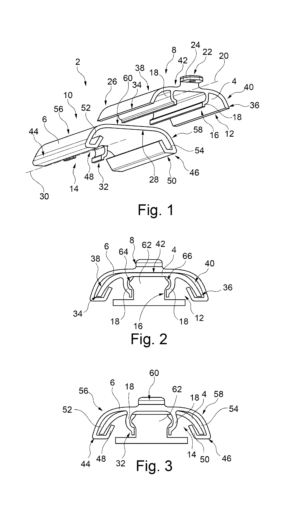
[0037]FIG. 1 shows a rail covering 2 for a sliding seat rail (not shown in this illustration). The rail covering 2 has a first elongate covering element 4 and a second elongate covering element 6. The two covering elements 4 and 6 have an upper side 8 and 10 and a lower side 12 and 14, respectively.

[0038]Virtually over its entire length on the lower side, the first covering element 4 has a first guide means 16 which is designed in the form of two web-like, spaced-apart projections 18. The two projections 18 run parallel to a longitudinal axis 20 and are of mirror-symmetrical design. Regions of the projections 18 that face the upper side 8 of the first covering element 4 are outwardly curved transversely with respect to the longitudinal axis 20.

[0039]In addition, the first covering element 4 has a first fastening end 22 on which a flange 24 is positioned, the flange facing away from the lower side 12. The flange serves to connect the first covering element 4 to a structural element t...


PUM


Abstract

A rail covering for a sliding seat rail between two passenger seats in a cabin of a vehicle has a first and a second elongate covering element. The first and second covering elements are formed complementary with respect to each other, allowing the first covering element to telescopically engage with a lower side of the second covering element. The first covering element has, at least in regions on a lower side, a first guide which displaceably holds the first covering element on the sliding seat rail along the main direction of extent thereof. The second covering element has an open end arranged on the end side and, at an end arranged oppositely on the end side on a lower side, has a second guide which displaceably holds the second covering element on the sliding seat rail along the main direction of extent thereof.

Description

CROSS-REFERENCES TO RELATED APPLICATIONS[0001]This application claims the benefit of the German patent application No. 102018108296.7 filed on Apr. 9, 2018, the entire disclosures of which are incorporated herein by way of reference.FIELD OF THE INVENTION[0002]The invention relates to a rail covering for a sliding seat rail between two passenger seats in a cabin of a vehicle.BACKGROUND OF THE INVENTION[0003]In vehicles which serve for transporting passengers, floor rails are often used for fastening passenger seats and other fittings in a variable position. In addition, it is known, in particular in aircraft, in accordance with demand or temporary requirements, to determine a distance between seats following one another in a longitudinal direction and optionally occasionally or regularly changing the distance. For this purpose, locking devices of relevant seats are released, the seats are then displaced along the floor rail, and the locking devices are locked again. Changing the dis...

Claims


Application Information

Patent Timeline
Patent Type & Authority Applications(United States)
IPC IPC(8): B60N2/07B64D11/06
CPCB60N2/0725B64D11/0696B64D11/0639B64C1/18
Inventor GROSS, CLAUS-PETER
Owner AIRBUS OPERATIONS GMBH
Why Eureka
Try Eureka