Adaptive comfort control system

a comfort control and adaptive technology, applied in the field of hvac systems, can solve the problems of increasing the cost of providing human comfort, occupants being uncomfortable, and being unable to sense changes (both internal and external to a treated space) that directly affect the comfort of occupants, and achieve the effect of maximizing energy savings

Active Publication Date: 2019-10-10
AIR2O INC +1
View PDF0 Cites 32 Cited by
  • Summary
  • Abstract
  • Description
  • Claims
  • Application Information

AI Technical Summary

Benefits of technology

[0015]Aspects of the present invention also provide for predictive modeling to allow the comfort management system to provide optimal comfort and maximize energy savings based on changes to the comfort target. For example, aspects of the invention further comprise predicting when a member of the comfort target is predicted to arrive at a location within an area proximate to the defined treatment region, and may be accomplished, for example, by accessing the comfort target's stored schedule, by receiving an input from a mobile device in possession of the comfort target, by tracking an input from a vehicle navigation system used by the comfort target, by receiving an SMS text message sent from the comfort target's mobile device, by computing an estimated time of arrival of the comfort target based on a current location of the comfort target and the comfort target's mode of travel, and from receiving and input from an app installed on the mobile device in possession of the comfort target. Additionally in various embodiments, predictio

Problems solved by technology

A longstanding problem in the operation of heating, ventilating and air conditioning (HVAC) equipment is efficient operation of equipment controls, including the temperature sensor or thermostat.
This presents a challenge in conditions of changing indoor and outdoor temperatures, humidity levels, occupancy of areas maintained by HVAC equipment, and comfort levels of the occupants.
While human occupant comfort is a goal the HVAC industry strives to achieve, without out a more comprehensive view of comfort provision as a system, the cost to provide human comfort can grow precipitously when environmental challenges arise.
Regulating indoor temperature based this single factor does not maximize energy savings as the seasons vary and use of the treated area varies, and may also lead to occupants being uncomfortable at least part of the time.
Further, even so-called “smart” thermostats of prior systems fail to predict the impact of various environmental factors on

Method used


Image

  • Adaptive comfort control system
  • Adaptive comfort control system
  • Adaptive comfort control system

Examples


Embodiment Construction

[0036]While various embodiments of the present invention are described herein, it will be apparent to those of skill in the art that many more embodiments and implementations are possible that are within the scope of this invention. Accordingly, the present invention is not to be restricted except in light of the attached claims and their equivalents.

[0037]In the present disclosure, the words “a” or “an” are to be taken to include both the singular and the plural. Conversely, any reference to plural items shall, where appropriate, include the singular.

[0038]The present technology may be described in terms of functional block components and various processing steps. Such functional blocks may be realized by any number of hardware or software components configured to perform the specified functions and achieve the various results. For example, the present technology may employ systems, technologies, devices, algorithms, designs, services, and the like, which may carry out a variety of...


PUM


Abstract

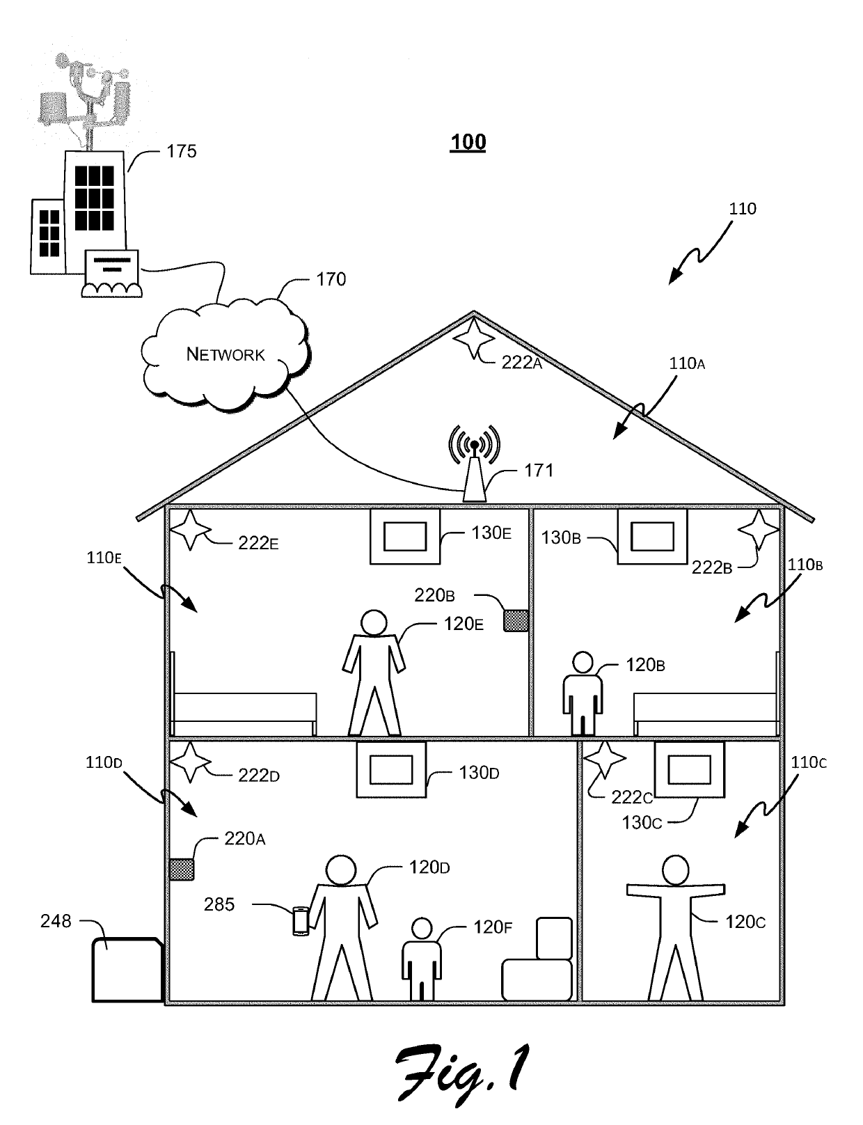
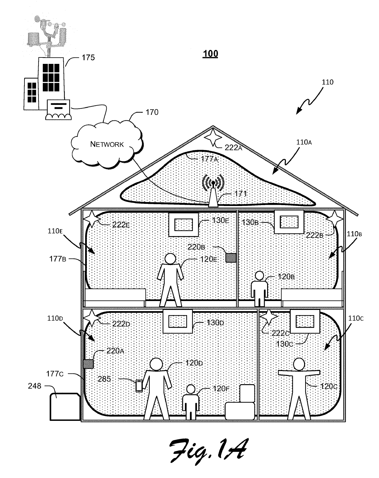
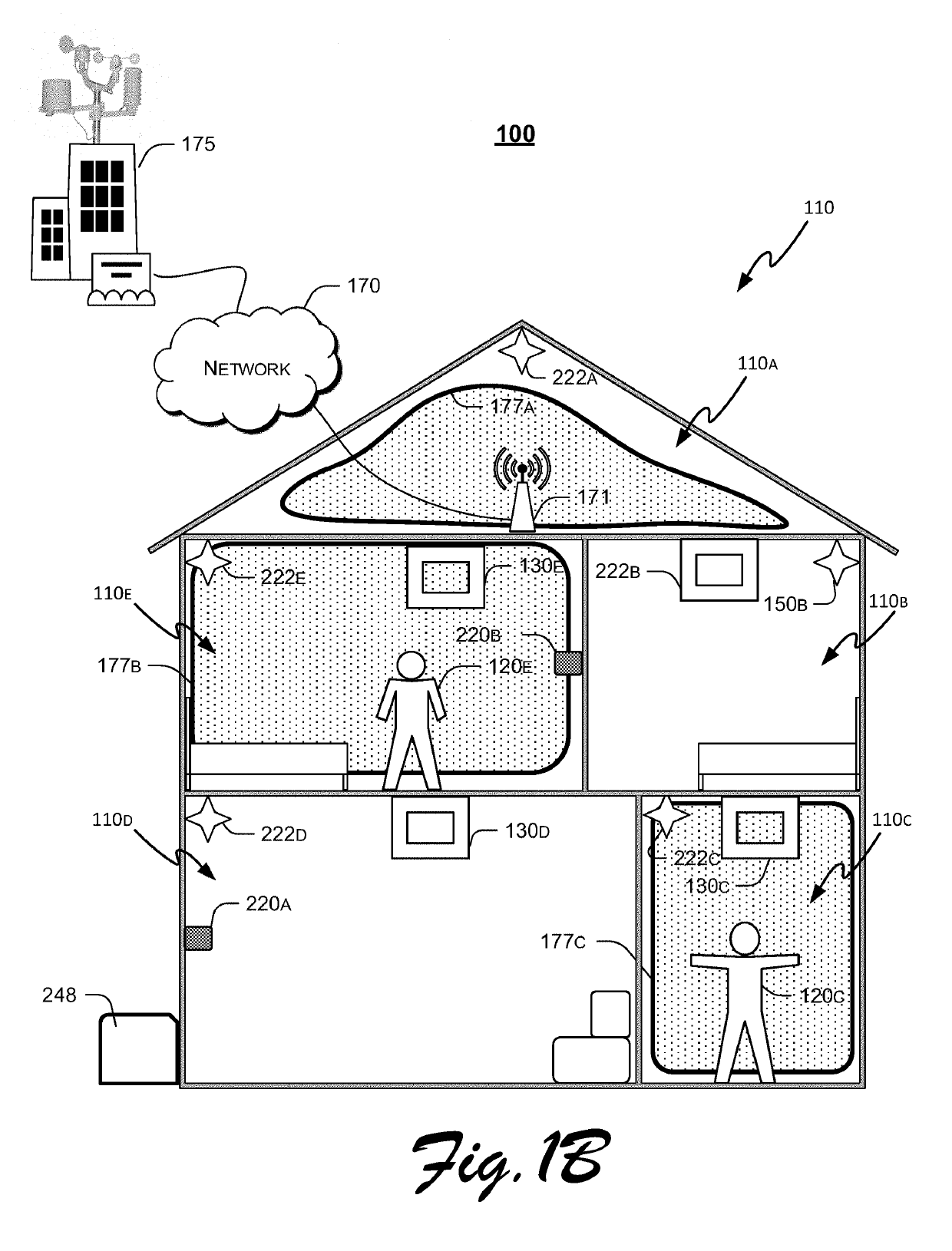
There is provided a comfort management system including a networked comfort management control device. The comfort management control device operates an HVAC interface to maintain an environment utilizing a determined comfort zone range for one or more occupants of an area treated by the HVAC system, and utilizes controlled deviations from an initial set point to maintain comfort while maximizing energy efficiency of the HVAC system.

Description

FIELD AND BACKGROUND OF THE INVENTIONField of the Invention[0001]The present invention relates generally to heating, ventilation, and air conditioning (“HVAC”) systems. More particularly, the present invention relates to an HVAC system that adaptively maintains a defined and adjustable comfort zone.BACKGROUND OF THE INVENTION[0002]A longstanding problem in the operation of heating, ventilating and air conditioning (HVAC) equipment is efficient operation of equipment controls, including the temperature sensor or thermostat. This presents a challenge in conditions of changing indoor and outdoor temperatures, humidity levels, occupancy of areas maintained by HVAC equipment, and comfort levels of the occupants. While human occupant comfort is a goal the HVAC industry strives to achieve, without out a more comprehensive view of comfort provision as a system, the cost to provide human comfort can grow precipitously when environmental challenges arise. In many climates, heating and cooling...

Claims


Application Information

Patent Timeline
IPC IPC(8): F24F11/46F24F11/52F24F11/56F24F11/64F24F11/65F24F11/72G05B13/04
CPCF24F11/64F24F2110/40F24F11/52F24F11/56H04L12/2807F24F11/65F24F2110/10F24F2110/20F24F2120/12F24F11/72F24F11/46H04L12/2816F24F2110/12F24F2110/22F24F2130/10G05B13/048H04L12/282H04L12/2827G05B2219/2642G05B15/02
Inventor SALEM, MOHAMED FAROUKSULLIVAN, MICHAEL ROBERT
Owner AIR2O INC
Why Eureka
Try Eureka