Imaging lens
a technology of imaging and lens, applied in the field of imaging lenses, can solve the problems of inability to obtain excellent optical performance, difficult to correct aberrations at a peripheral area, etc., and achieve the effects of low f-number, correcting aberrations properly, and high resolution
- Summary
- Abstract
- Description
- Claims
- Application Information
AI Technical Summary
Benefits of technology
Problems solved by technology
Method used
Image

Examples
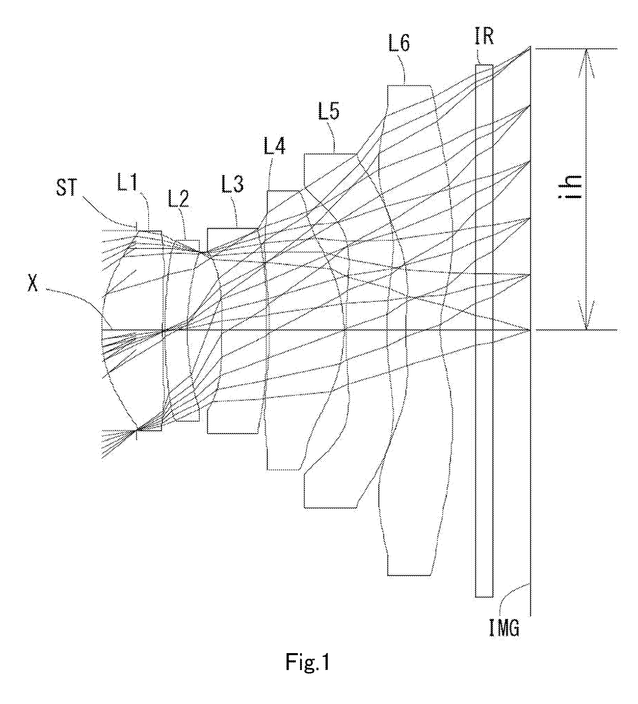
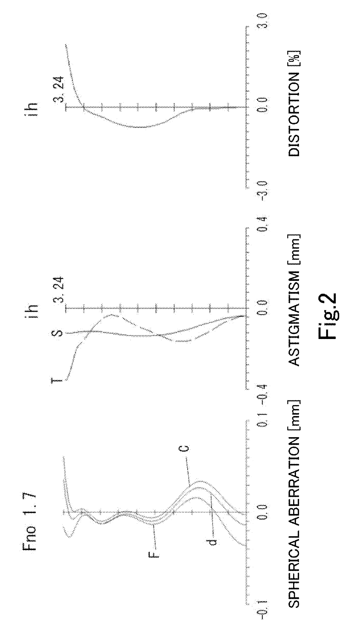
example 1
[0091]The basic lens data is shown below in Table 1.
TABLE 1Example 1Unit mmf = 3.90Fno = 1.7ω(°) = 38.9ih = 3.24TTL = 4.86Surface DataSurfaceCurvatureSurfaceRefractiveAbbeNumber iRadius rDistance dIndex NdNumber νd(Object)InfinityInfinity1 (Stop)Infinity−0.40302*1.59600.70381.54455.86 (νd1)3*5.19420.02504*3.15710.25971.66120.37 (νd2)5*2.98260.39816*−7.67600.51121.66120.37 (νd3)7*46.25550.03158*−7.79930.88101.53555.66 (νd4)9*−1.56940.023710* 9.61810.47201.61425.58 (νd5)11* 4.69440.213512* 3.19430.39841.53555.66 (νd6)13* 1.23850.400014 Infinity0.21001.51764.2015 Infinity0.4203Image PlaneInfinityConstituent Lens DataLensStart SurfaceFocal LengthComposite Focal Length123.960f3456−12.12624−200.22636−9.926483.505510−15.495612−4.071Aspheric Surface DataSecond SurfaceThird SurfaceFourth SurfaceFifth SurfaceSixth SurfaceSeventh Surfacek0.000000E+00 0.000000E+00 0.000000E+00 0.000000E+000.000000E+00 0.000000E+00A4−2.494665E−02 −4.581553E−01−5.019561E−01−4.514179E−021.438016E−02−2.181993E−01A6...
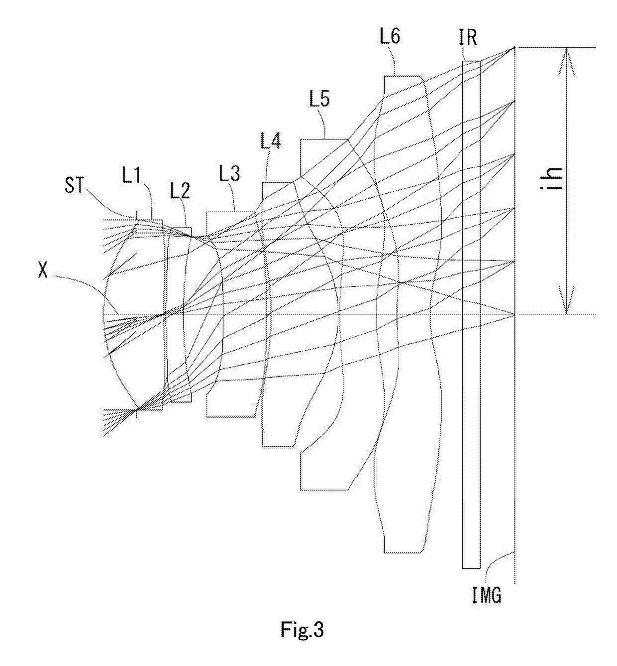
example 2
[0094]The basic lens data is shown below in Table 2.
TABLE 2Example 2Unit mmf = 3.90Fno = 1.7ω(°) = 39.0ih = 3.24TTL = 4.91Surface DataSurfaceCurvatureSurfaceRefractiveAbbeNumber iRadius rDistance dIndex NdNumber νd(Object)InfinityInfinity1 (Stop)Infinity−0.40192*1.63500.72921.54455.86 (νd1)3*5.70210.02514*5.28170.21001.66120.37 (νd2)5*4.72950.48606*−10.71710.52001.66120.37 (νd3)7*53.30910.05308*−5.06410.82081.53555.66 (νd4)9*−1.32750.020010* 9.30470.44021.61425.58 (νd5)11* 3.16450.247812* 2.97560.39821.53555.66 (νd6)13* 1.25910.400014 Infinity0.21001.51764.2015 Infinity0.4224Image PlaneInfinityConstituent Lens DataLensStart SurfaceFocal LengthComposite Focal Length123.961f3456−16.20424−80.66836−13.461483.125510−8.026612−4.440Aspheric Surface DataSecond SurfaceThird SurfaceFourth SurfaceFifth SurfaceSixth SurfaceSeventh Surfacek0.000000E+00 0.000000E+00 0.000000E+00 0.000000E+00 0.000000E+00 0.000000E+00A42.219251E−02−2.976772E−01−3.056814E−01−3.452550E−02−1.649320E−01−2.494229E−01A6...
example 3
[0097]The basic lens data is shown below in Table 3.
TABLE 3Example 3Unit mmf = 3.91Fno = 1.7ω(°) = 39.0ih = 3.24TTL = 4.91Surface DataSurfaceCurvatureSurfaceRefractiveAbbeNumber iRadius rDistance dIndex NdNumber νd(Object)InfinityInfinity1 (Stop)Infinity−0.41482*1.61750.71371.54455.86 (νd1)3*5.74260.02524*5.13490.21001.66120.37 (νd2)5*4.23560.50156*−14.94830.43841.66120.37 (νd3)7*72.00360.05048*−4.75520.94771.53555.66 (νd4)9*−1.42150.020010* 4.77000.36581.61425.58 (νd5)11* 2.64000.278212* 3.05730.39931.53555.66 (νd6)13* 1.25520.400014 Infinity0.21001.51764.2015 Infinity0.4232Image PlaneInfinityConstituent Lens DataLensStart SurfaceFocal LengthComposite Focal Length123.899f3456−19.58324−40.35136−18.697483.450510−10.298612−4.315Aspheric Surface DataSecond SurfaceThird SurfaceFourth SurfaceFifth SurfaceSixth SurfaceSeventh Surfacek0.000000E+00 0.000000E+00 0.000000E+00 0.000000E+00 0.000000E+00 0.000000E+00A41.675830E−02−3.075204E−01−3.110407E−01−4.184615E−02−1.744960E−01−1.955987E−01A...
PUM
 Abstract
Description
Claims
Application Information
 - R&D
- Intellectual Property
- Life Sciences
- Materials
- Tech Scout
- Unparalleled Data Quality
- Higher Quality Content
- 60% Fewer Hallucinations
Browse by: Latest US Patents, China's latest patents, Technical Efficacy Thesaurus, Application Domain, Technology Topic, Popular Technical Reports.
© 2025 PatSnap. All rights reserved.Legal|Privacy policy|Modern Slavery Act Transparency Statement|Sitemap|About US| Contact US: help@patsnap.com