
Spring-loaded leg base

Inactive Publication Date: 2019-10-17
ZENITHEN USA
View PDF4 Cites 0 Cited by
  • Summary
  • Abstract
  • Description
  • Claims
  • Application Information

AI Technical Summary

Benefits of technology

The invention is a new design for a spring-loaded leg base. The technical effect of the design is to provide a more efficient and flexible connection between the seat frame and the spring, using a protean spring that automatically adjusts to the changing angles of the chair during rocking, and a grooved track design on the base to guide the connecting components. This results in improved comfort, durability, and reduced noise for the user. Additionally, the design allows for easy assembly and disassembly of the chair frame and spring.

Problems solved by technology

This causes the chair to remain in an unstable condition all the time, limiting its use to only certain leisure occasions.
But this mechanism is difficult to achieve in reality.
Also, because the bottom part of the sleeve housing that touches the ground is constrained by the ground, it is unable to follow the angle of the leg components to make timely changes.
This causes the lower end of the leg components to be stuck inside the sleeve housing and unable to function normally, so that either the rocking function is lost or the rocking movement is not smooth.

Method used


Image

  • Spring-loaded leg base
  • Spring-loaded leg base
  • Spring-loaded leg base

Examples


Embodiment Construction

)

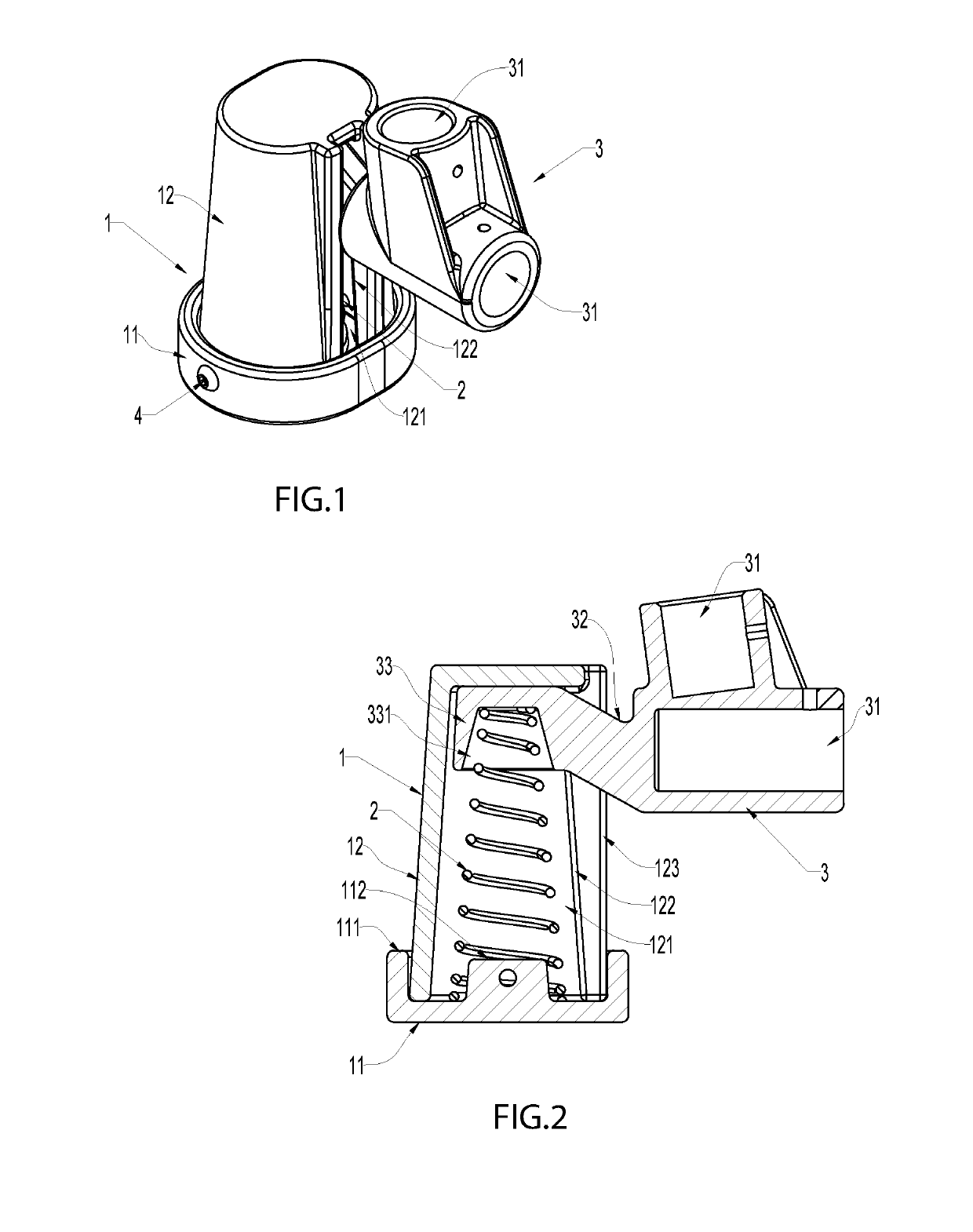
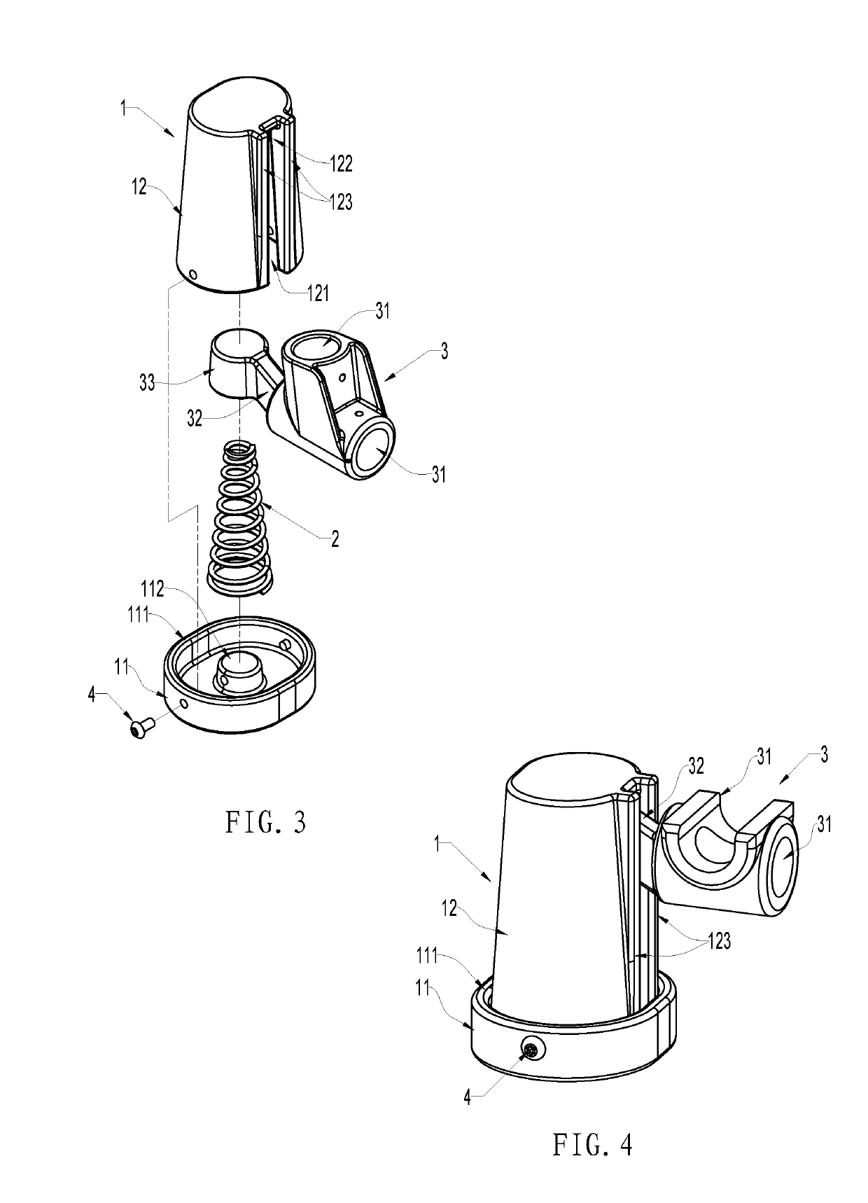
[0045]Referring to FIGS. 1-3, a type of spring-loaded leg base is shown including a base 1, a spring 2, and a connecting component 3.

[0046]Base 1 has a chamber with a hollow structure. Specifically, base 1 is a separate structure which includes two parts: a base bottom 11 and a cylindrical housing 12. The perimeter of the base bottom 11 is molded with an enclosing sleeve 111. The center is molded with a protruding console 112. The cylindrical housing 12 is molded with a chamber 121 that has an opening and a grooved track 122. The grooved track 122 is parallel to the central axis of the chamber 121. On the two sides of the grooved track 122, there are guiding lips 123 that protrude outwardly. The lower part of the cylindrical housing 12 is mounted inside the enclosing sleeve 111 of the base bottom 11 and secured by a screw 4 or other fastener. Of course, an alternative option is for the base 11 to be on top, the cylindrical housing 12 at the bottom, and the cylindrical housing 12 to...


PUM


Abstract

A type of spring-loaded leg base includes a base, a spring, and a connecting component. The base has a hollow chamber. The spring is placed inside the chamber. The connecting component is a unified component of a leg sleeve, a connecting bar and a spring cap. By passing the connecting bar through the grooved track and placing the spring cap on the top of the spring, the leg sleeve can be locked in position on the chair frame to create flexible support. This mechanism creates the rocking function for a regular chair.

Description

BACKGROUND OF THE INVENTIONField of the Invention[0001]The present invention relates to a chair accessory, and more particularly to a type of spring-loaded leg base. The base is placed where the chair frame touches the ground so that the chair can rock properly.Technical Background[0002]A rocking chair is a common leisure facility that has a rocking feature. However, it typically relies on arched bar components to have contact with the ground to create rocking movements. This causes the chair to remain in an unstable condition all the time, limiting its use to only certain leisure occasions. As such, manufacturers have improved on its defect, so that rocking chairs can work in a stable mode and a rocking mode.[0003]For example, a collapsible and portable rocking chair disclosed in Published U.S. Patent Application Publication U.S.20150282625A1. It includes an expandable and collapsible seat frame. That seat frame consists of a pair of side frame components and a connecting bar that ...

Claims


Application Information

Patent Timeline
IPC IPC(8): A47C3/02A47C7/00
CPCA47C3/02A47C7/002
Inventor FRANKEL, ANDREW DAVIDZHENG, SHI-PINGZHENG, TIAN-XIA
Owner ZENITHEN USA
Features
  • Generate Ideas
  • Intellectual Property
  • Life Sciences
  • Materials
  • Tech Scout
  • Unparalleled Data Quality
  • Higher Quality Content
  • 60% Fewer Hallucinations
Learn More