A spacer structure for a saw disc assembly and a saw disc assembly

Pending Publication Date: 2019-03-28
HUSQVARNA AB
View PDF6 Cites 4 Cited by
  • Summary
  • Abstract
  • Description
  • Claims
  • Application Information

AI Technical Summary

Benefits of technology

[0005]An object of the invention is to improve the design of

Problems solved by technology

When manufacturing such a spacer structure, the material waste will be large due to the

Method used


Image

  • A spacer structure for a saw disc assembly and a saw disc assembly
  • A spacer structure for a saw disc assembly and a saw disc assembly
  • A spacer structure for a saw disc assembly and a saw disc assembly

Examples


Example

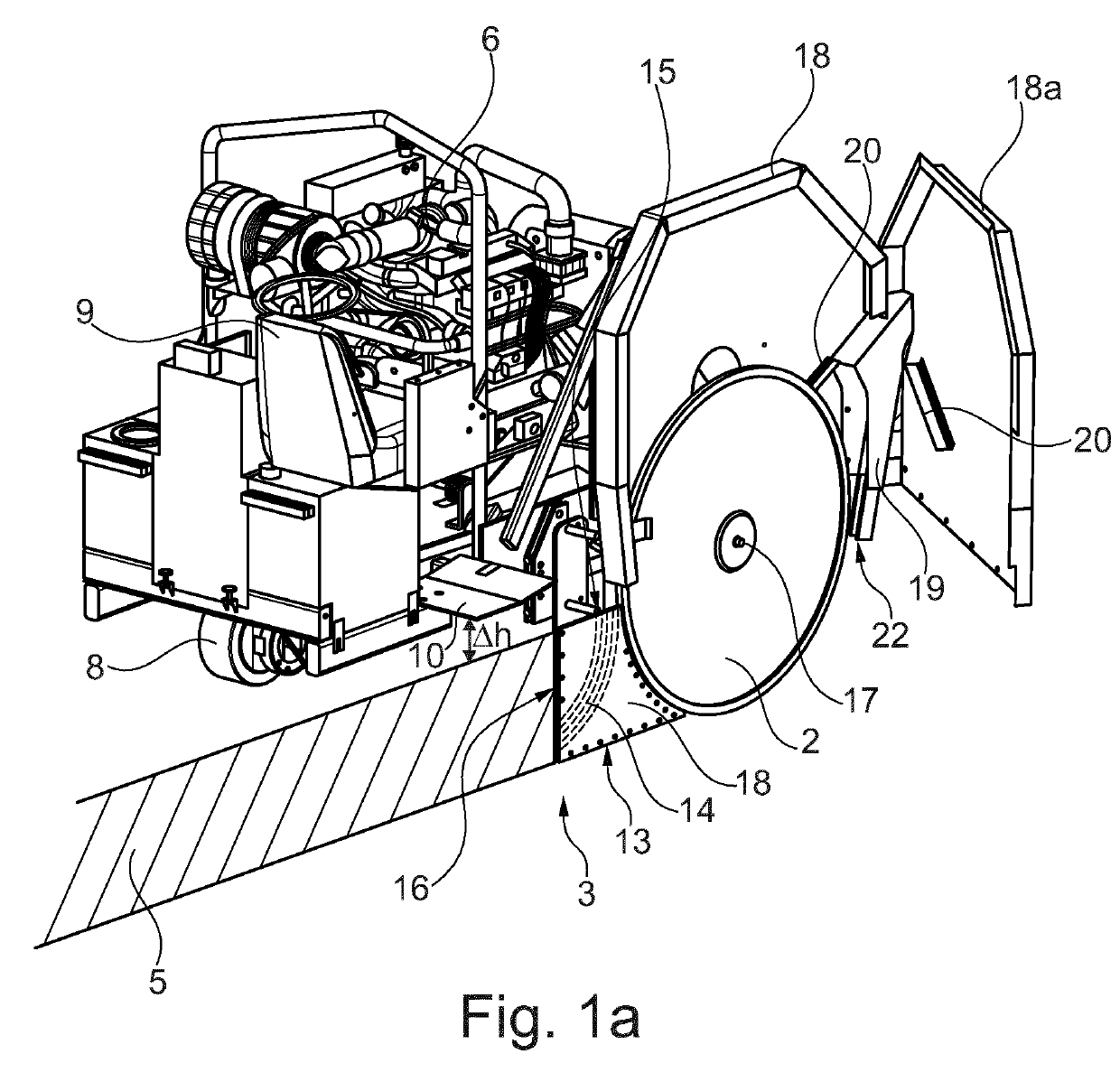
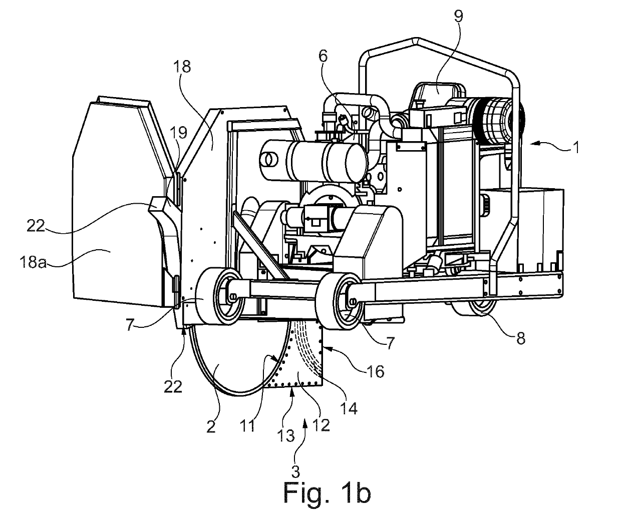
[0048]FIGS. 1a-1b show a laying machine 1 including a sawing machine 4 including a saw disc device 2 for making a trench 5 in the ground and a consolidation and laying means 3 for clearing and safeguarding the trench 5 from collapsing while laying at least one flexible casing or tube, cable or wire into the trench 5. The at least one flexible casing or tube, cable or wire can be rolled off from a not shown reel mounted on the machine 1. A disc guard 18 covers the portion of the saw disc device 2 that is above ground level.

[0049]The machine 1 shown in FIGS. 1a-1b has two front wheels 7 and a rear wheel 8. A motor 6, preferably a diesel engine, provides power to propel the machine 1. The motor 6 is also responsible for rotating the saw disc device 2, preferably through a belt transmission (not shown).

[0050]The saw disc device 2, the disc guard 18, and the consolidation and laying means 3 are mounted at a first side of the machine 1, here shown as the right hand side of the machine 1. ...


PUM


Abstract

A spacer structure (204; 205) for a saw disc assembly of a sawing machine (4), comprises a hub device (220) having a central axis and being adapted to be coaxially arranged between a pair of axially peripheral saw discs. According to the invention, said hub device (220) is configured and adapted to detachably or non-detachably receive a proximal portion (231) of an elongated spacer means (230) in a substantially radial manner in relation to said hub device, said elongated spacer means (230) being adapted to be arranged between said pair of saw discs, a distal portion (235) of said elongated spacer means (230) being constituted and adapted to detachably or non-detachably connect to said pair of peripheral saw discs.

Description

BACKGROUND[0001]The present invention relates to a spacer structure for a saw disc assembly of a sawing machine, comprising a hub device having a central axis and being adapted to be coaxially arranged between a pair of saw discs. It also relates to a spacer structure for a saw disc assembly of a sawing machine, comprising at least one elongated spacer means adapted to be arranged between a pair of axially peripheral saw discs in a substantially radial manner in relation to a central portion of said pair of peripheral saw discs. It furthermore relates to a spacer structure for a saw disc assembly of a sawing machine, comprising a hub device having a central axis and being adapted to be coaxially arranged between a pair of axially peripheral saw discs.[0002]It also relates to a saw disc assembly comprising a pair of axially peripheral saw discs having a common rotational axis and a central portion coaxial to said rotational axis, and furthermore provided with such a spacer structure....

Claims


Application Information

Patent Timeline
IPC IPC(8): E02F5/08E02F5/14F16L1/032H02G1/06
CPCE02F5/08E02F5/14F16L1/032H02G1/06E02F5/10B23D61/026B27B5/34
Inventor NILSSON, TOBIASSJODAHL, FREDRIK
Owner HUSQVARNA AB
Why Eureka
Try Eureka