Femoral Nail With Enhanced Bone Conforming Geometry

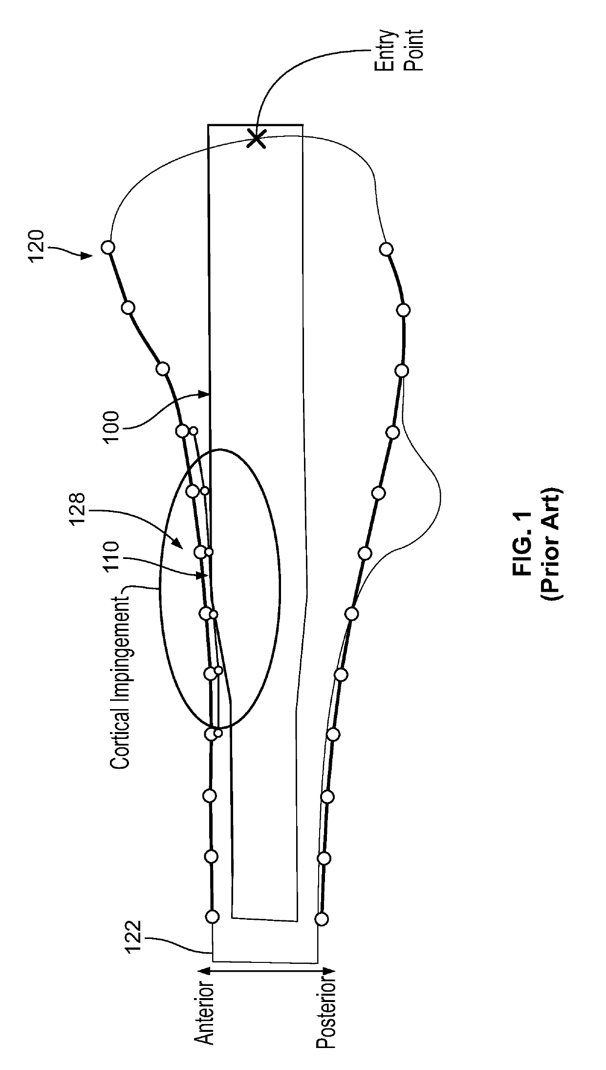
a femoral nail and geometry technology, applied in the field of femoral nail with enhanced bone conforming geometry, can solve the problems of immobilizing fractured bone, difficult to develop appropriate femoral nail geometries that are suitable for the entire patient population, and internal devices, and achieve the effect of reducing the incidence of femoral cortex impingemen

Active Publication Date: 2019-10-17
STRYKER EURO OPERATIONS HLDG LLC
View PDF1 Cites 3 Cited by
  • Summary
  • Abstract
  • Description
  • Claims
  • Application Information

AI Technical Summary

Benefits of technology

[0005]A femoral nail is disclosed that includes a proximal section, a distal section, and an intermediate section. The proximal and distal sections extend along their own axes and are substantially straight. The intermediate section is disposed between the proximal section and distal section and includes a first curved portion, a straight portion, and a second curved portion. The straight portion is disposed between the first and second curved portions. The second curved portion is curved in a first plane and has a radius that substantially matches a radius of an anterior bow of a patient's femur as may be approximated based upon a database population analysis. The first curved portion is curved in the first plane and also in a second and third plane. The second plane intersects the first plane at an oblique angle, and the third plane is a resultant of this oblique angle and the magnitude of the bends of the nail in the first and second planes. Such multiplane curvature has been determined by database analysis to provide optimal fit for the general patient population and to reduce incidence of femoral cortex impingement.

Problems solved by technology

Such fractures often require internal devices to reduce and immobilize the fractured bone.
However, since anatomy varies from patient to patient, it has been difficult to develop appropriate femoral nail geometries that are suitable for the entire patient population.
This disproportionality may result in impingement of the femoral cortex during implantation potentially resulting in fracture and also malalignment of the femoral nail which can be uncomfortable for the patient and result in less than desirable outcomes.

Method used


Image

  • Femoral Nail With Enhanced Bone Conforming Geometry
  • Femoral Nail With Enhanced Bone Conforming Geometry
  • Femoral Nail With Enhanced Bone Conforming Geometry

Examples


Embodiment Construction

[0026]When referring to specific directions in the following discussion of certain implantable devices, it should be understood that such directions are described with regard to the implantable device's orientation and position during exemplary application to the human body. Thus, as used herein, the term “proximal” means close to the heart and the term “distal” means more distant from the heart. The term “inferior” means toward the feet and the term “superior” means toward the head. The term “anterior” means toward the front of the body or the face and the term “posterior” means toward the back of the body. The term “medial” means toward the midline of the body and the term “lateral” means away from the midline of the body. Also, as used herein, the terms “about,”“generally” and “substantially” are intended to mean that slight deviations from absolute are included within the scope of the term so modified.

[0027]FIG. 10 depicts an exemplary left leg femur. The femur has a proximal fe...


PUM


Abstract

A femoral nail includes a proximal section, a distal section remote from the proximal section, and an intermediate section disposed between the proximal section and distal section and having first and second curved portions. The first curved portion is positioned closer to the proximal section than the second curved portion. The second curved portion is curved in a first plane, and the first curved portion is curved in the first plane and a second and third plane.

Description

CROSS-REFERENCE TO RELATED APPLICATIONS[0001]This application claims the benefit of the filing date of U.S. Provisional Patent Application No. 62 / 657,279, filed on Apr. 13, 2018, the disclosure of which is hereby incorporated by reference.BACKGROUND OF THE INVENTION[0002]The skeletal system includes several long bones including the femur. The femur is the longest of the long bones and is generally divided into three regions: the proximal femur, distal femur, and femoral shaft. Femoral fractures, which are commonly caused by acute trauma, can occur at or between any one of these regions. Such fractures often require internal devices to reduce and immobilize the fractured bone.[0003]One such device is a femoral, intramedullary nail. Femoral nails are elongate structures that are inserted into an intramedullary canal through either the proximal femur or distal femur. Such nails are typically bent along their respective lengths in an attempt to follow the natural curvature of a human lo...

Claims


Application Information

Patent Timeline
Patent Type & Authority Applications(United States)
IPC IPC(8): A61B17/72A61B17/92
CPCA61B17/7233A61B17/7283A61B17/921A61B17/72A61B17/748A61B2017/564A61B17/74
Inventor PETERSIK, ANDREASKLUEVER, HENDRIKRICCIARDI, GIOVANNI
Owner STRYKER EURO OPERATIONS HLDG LLC
Why Eureka
Try Eureka