
Method for smoother tonal response in flexographic printing

a flexographic printing and tonal response technology, applied in the field of printing, can solve the problems of strong discontinuity between solid and near-solid, rejection of printed artwork, and inability to achieve the effect of smoothing tonal response, and achieve the effect of improving highlights

Active Publication Date: 2019-10-17
ESKO SOFTWARE BV
View PDF0 Cites 11 Cited by
  • Summary
  • Abstract
  • Description
  • Claims
  • Application Information

AI Technical Summary

Benefits of technology

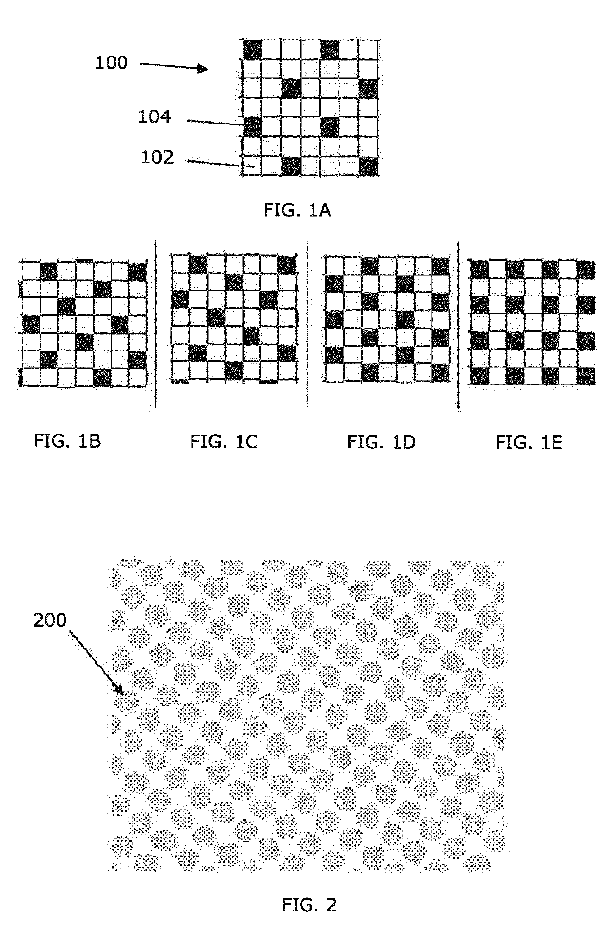
The invention is a process for creating a flexographic plate or mask for printing using a screen. The process involves selectively modulating the size of physical spots on the mask created by a laser based on a screen with a resolution defined by a base pattern of equally sized screen spots. The resulting plate or mask has one or more regions with a first high resolution base pattern and one or more regions with a second high resolution base pattern. The technical effect of the invention is to improve the quality of ink transfer in press by optimizing the size of the unexposed area between the spots.

Problems solved by technology

This realized benefit however creates a new problem: the remarkable boost of the solid rendering creates a strong discontinuity between the solid and the near-solids.
Consequently, this problem leads to rejection of printed artwork.
A disadvantage of this method, however, is that the benefits of the rendering boost may be missed in important places.
Highly saturated colors may not be reached because saturated colors often including at least one printing ink having a high density.
The synthetically different treatment of the flat tints compared to the other regions again may show a discontinuity in the final printed result.
Detecting discontinuities of this type may require scanning the entire page description with a highly specialized (typically slow) algorithm, and even when detected, there may be no suitable solution.
This moiré pattern may be rejected by print buyers as it is often very noticeable to the human naked eye.
But, given that very well calculated frequencies and angles for the solid boosting pattern generally must be chosen to avoid moiré patterns, the chosen frequencies and angles for avoiding moiré patterns may not be optimal for solid boosting.
Additionally, the highly non-linear behavior of flexographic plate making and printing also mean that when solid patterns fade, into near-solid screening areas, the resulting tonal curve does not always linearly fade, as might be desired.
In general, for example, half the pattern may not boost half the density, and it may boost not at all or even work in reverse.
Also the addition of the conventional screen dots may disturb the pattern in such a way that it no longer works as desired.
Attempts to avoid disturbing the pattern with the screen dots by keeping a protection one between patterns may add yet another complication that risks further disturbing the solid rendering effect.
Another problem very well known in flexography is that of (near) dot touching.
This may lead to a strong ‘tonal jump’ at a hard-to predict density.

Method used


Image

  • Method for smoother tonal response in flexographic printing
  • Method for smoother tonal response in flexographic printing
  • Method for smoother tonal response in flexographic printing

Examples


example

[0072]Exemplary computer code for performing the foregoing operations follows:

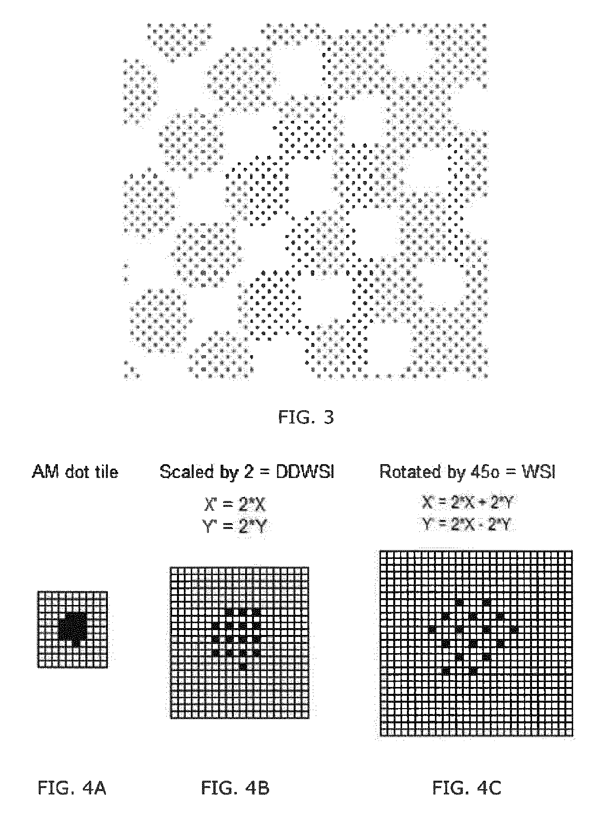
Tile CreateWSITile(Tile const & inOriginalTile)  {   / / 1. Calculate tile geometry parameters of WSI tile,   / /  based on original tile geometry  int A_WSI = 2 * inOriginalTile.A + 2 * inOriginalTile.B;  int B_WSI = 2 * inOriginalTile.A − 2 * inOriginalTile.B;  int M_WSI = inOriginalTile.M;  int N_WSI = inOriginalTile.N;   / / 2. Create WSI tile and reset thresholds of all pixels to maxlevel   / /  (pixels will never be switched on)  Tile WSITile(A_WSI, B_WSI, M_WSI, N_WSI);  for (int v_wsi = 0; v_wsi     for (int h_wsi = 0; h_wsi        / / verifies if coordinates are within the tilted WSI tile      if (!WSITile.IsWithinTileBound(v_wsi, h_wsi))        continued;       / / set threshold of pixel at coordinates v,h to maximum threshold;       / /   the pixel will never be switched on      WSITile.thresholds[v_wsi][h_wsi].SetToMaximum( );    }  }   / / 3. Copy each threshold of the original tile to WSI tile  for (int v_ori...


PUM


Abstract

A process for creating a flexographic plate or a mask for producing a flexographic plate, including providing a screen having a resolution defined by a base pattern of equally sized screen spots, each screen spot comprising a smallest exposed discrete element represented on the screen. In at least a non-solid tonal portion of the plate or mask, the size of physical spots are selectively modulated such that each set of four neighboring physical spots in the base pattern has an unexposed area centered therebetween. Each screen spot in the base pattern may be an exposed pixel surrounded by 8 unexposed pixels, each physical spot corresponding to the resolution of a laser beam for exposing the spots on the mask, in which the imaging step includes boosting power of the laser beam for isolated pixels relative to non isolated pixels. Mask and plates, and imaging systems for creating them, are also disclosed.

Description

CROSS REFERENCE TO RELATED APPLICATIONS[0001]This application claims priority to PCT Application Ser. No PCT / EP2017 / 062769, filed May 26, 2017, which claims priority from U.S. Provisional Application No. 62 / 342,475, filed May 27, 2016, which are herein incorporated by reference in their entireties.BACKGROUND OF THE INVENTION[0002]The invention relates to printing, more specifically to flexographic printing, and methods, and systems for implementation of such methods, for improving the tonal response curve of a printing plate, including plate making methods.[0003]Traditionally, flexographic plates have a flat upper level surface for printing solid areas, a flat lower surface for leaving the substrate unprinted and a number of mathematically organized printing dots at the upper level (the level that physically touches the printing medium onto which the printed image is transferred) with a size corresponding to the density to be reproduced. One printing method is called AM (amplitude m...

Claims


Application Information

Patent Timeline
IPC IPC(8): B41M1/04G03F7/20H04N1/405B41N1/12
CPCB41M1/04B41N1/12H04N1/405G03F7/2053G03F1/80G03F1/00G03F7/202
Inventor MORISSE, PETERSIEVERS, WOLFGANG
Owner ESKO SOFTWARE BV
Learn More