
Eureka
For R&D, Eureka makes reading and utilizing patents & technical documents easy.
Eureka AIR
Designed for self-driven R&D workflows. Generate viable solutions, solve complex R&D challenges, empower your innovation with AI.

Eureka Materials
Designed for material experts only. Revolutionize your material R&D, from search, analyze, to developing new materials.

TechResearch
Generate reliable direction feasibility study reports for your R&D in just a few steps.

TechSeek
Discover and master advanced knowledge NOW. Basics, ideas, possibilities, all at once.

TechMind
As an expert in R&D Theories, TechMind can generates customized viable solutions instantly.

TechRisk
Analyze your overall solution with one click, know your potential R&D risks in advance.

TechMonitor
Get weekly tech updates, stay abreast of the latest tech innovations and key insights.
Method and machine for treating a tired wheels
- Summary
- Abstract
- Description
- Claims
- Application Information
AI Technical Summary
Benefits of technology
Problems solved by technology
Method used
Image

Examples
Embodiment Construction
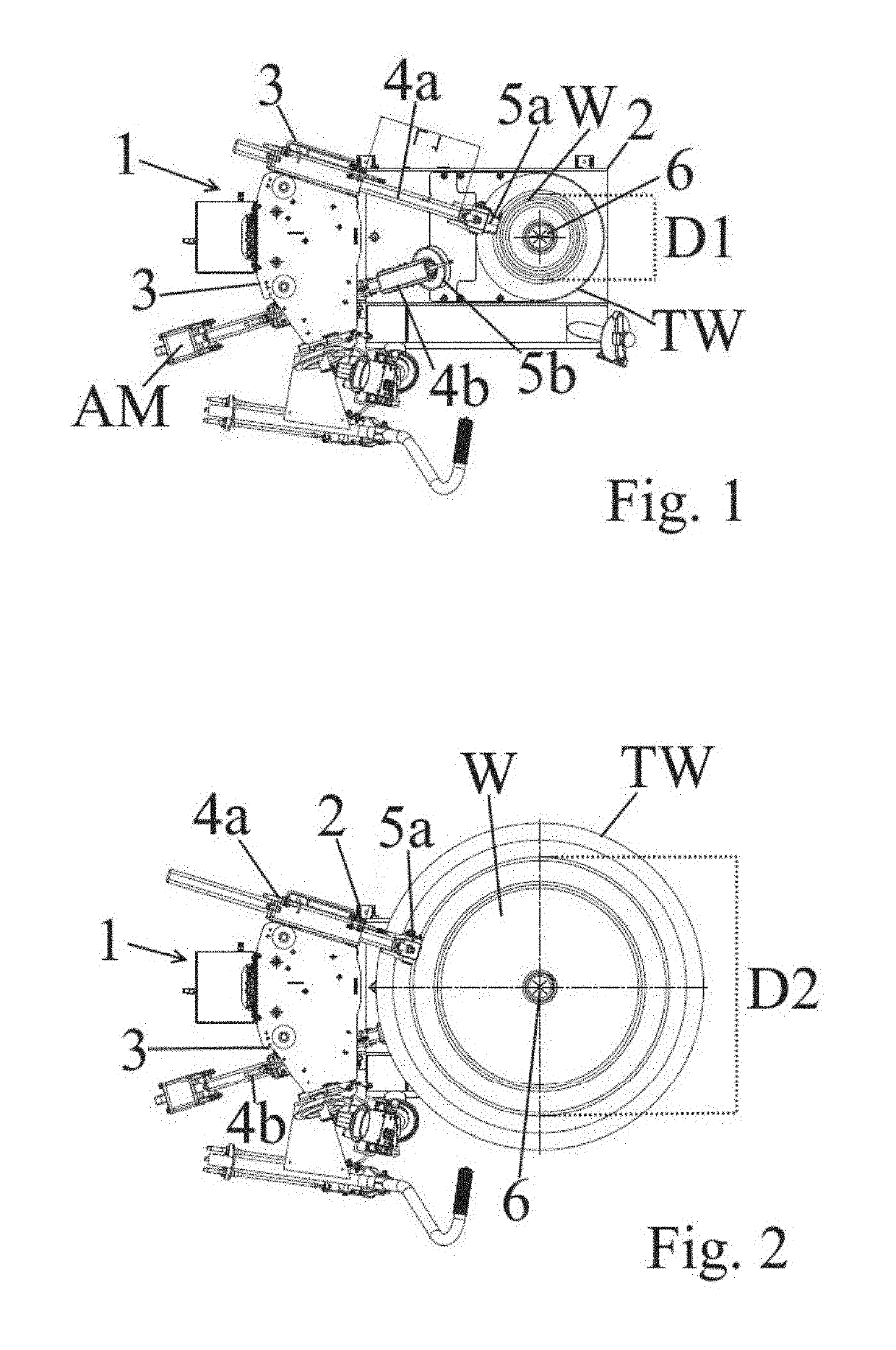
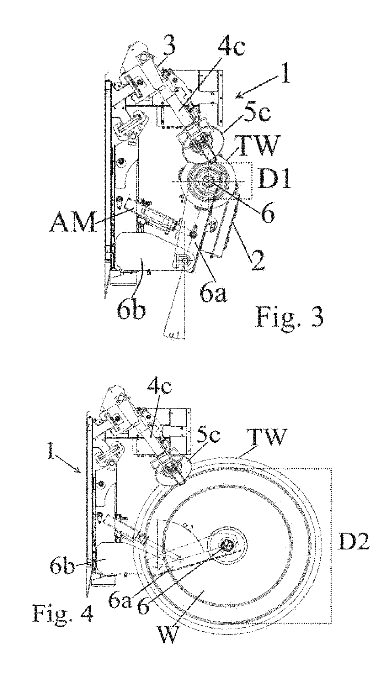
[0021]With reference to the accompanying figures, a machine 1 for treating a tired wheel TW according to the present invention comprises at least a base 2, at least a column 3 projecting from the base 2, at least one tool-holder arm 4a, 4b, 4c supported by the column 3 and one or more work tools 5a, 5b, 5c such as a bead removal roller and / or a mounting and / or dismounting tool, supported by or articulated to a respective tool-holder arm 4a, 4b, 4c.
[0022]Actuator means AM are provided, such as hydraulic, pneumatic, electric or other actuators, of one or more arms 4a, 4b, 4c for their displacement along the column or the respective column 3 and / or pivoting with respect to the column 3, as well as any actuator means, such as hydraulic, pneumatic, electric or other actuators, of one or more work tools 5a, 5b, 5c with respect to the respective arm 4a, 4b, 4c.
[0023]Clearly, one or more tools may also be idly pivoted to the respective arm or one or more tools may be articulated or pivote...
PUM
 Abstract
Description
Claims
Application Information
 - R&D Engineer
- R&D Manager
- IP Professional
- Industry Leading Data Capabilities
- Powerful AI technology
- Patent DNA Extraction
Browse by: Latest US Patents, China's latest patents, Technical Efficacy Thesaurus, Application Domain, Technology Topic, Popular Technical Reports.
© 2024 PatSnap. All rights reserved.Legal|Privacy policy|Modern Slavery Act Transparency Statement|Sitemap|About US| Contact US: help@patsnap.com