
Liquid container and liquid consumption device

Active Publication Date: 2019-10-17
SEIKO EPSON CORP
View PDF3 Cites 0 Cited by
  • Summary
  • Abstract
  • Description
  • Claims
  • Application Information

AI Technical Summary

Benefits of technology

The present invention provides a liquid container for a liquid consumption device. The liquid container is designed to store and supply liquid to the device. It includes a storage portion with undulation reduction, a support portion, and a gravity direction. The container allows the liquid to flow smoothly and ensures that the liquid level remains stable during use. This design improves the efficiency of liquid consumption and reduces the likelihood of blockages or splashing.

Problems solved by technology

When the air bubbles are supplied to the head together with the ink, it is likely that a failure in the jetting of the ink occurs and thus that dots are removed in a printed image.
However, it is likely that such members follow the movement of the undulation of the liquid so as not to sufficiently reduce the undulation of the liquid.
Moreover, depending on the position of the arrangement of the member or the posture of the arrangement thereof, the flow of the ink within the liquid container is inhibited, with the result that a failure in the supply of the ink to a liquid consumption device may occur.

Method used


Image

  • Liquid container and liquid consumption device
  • Liquid container and liquid consumption device
  • Liquid container and liquid consumption device

Examples


first embodiment

1. First Embodiment

1-1. Overall Configuration of Liquid Consumption Device

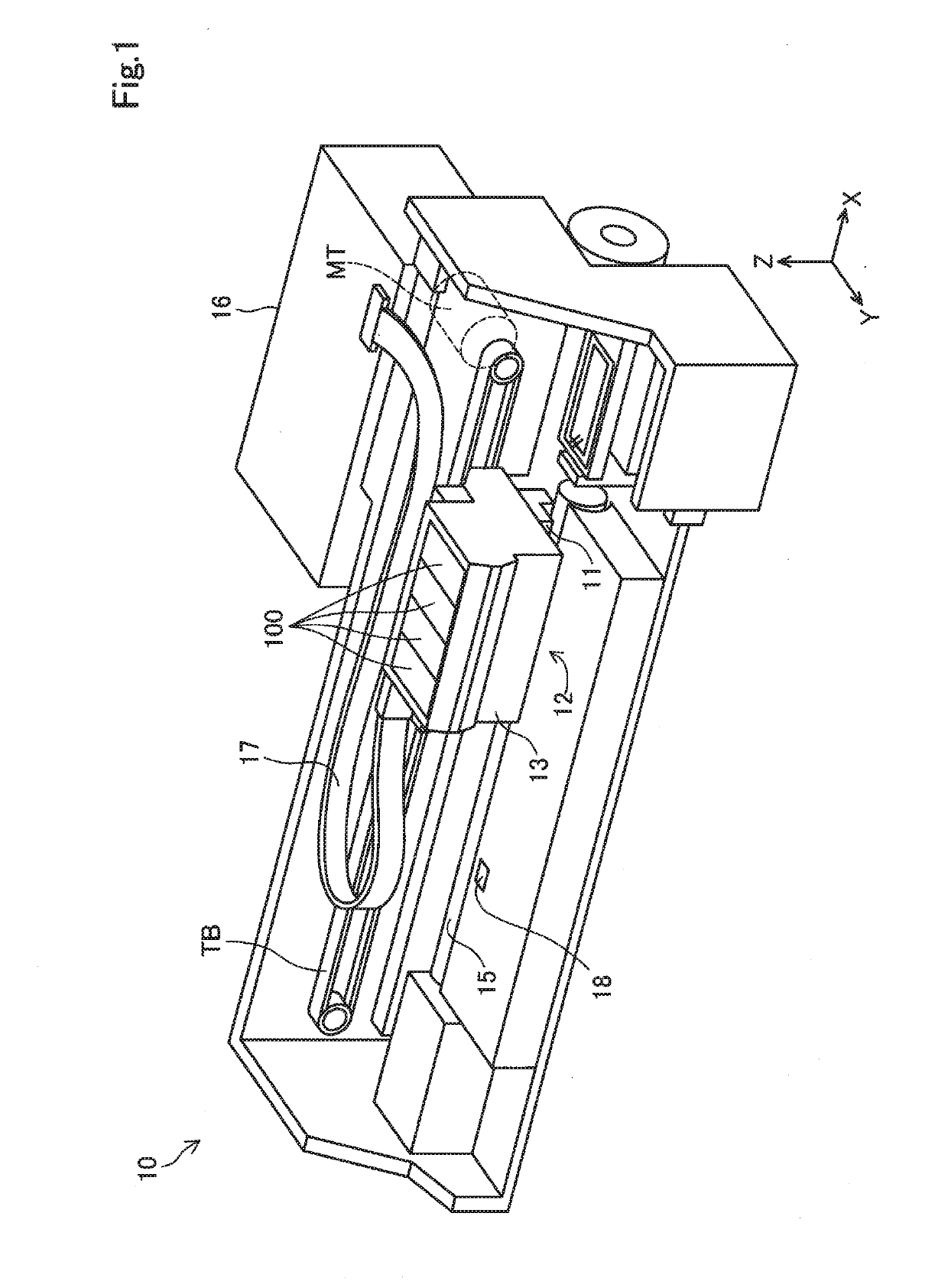
[0051]FIG. 1 is a schematic perspective view showing the configuration of a liquid consumption device 10 in a first embodiment. In FIG. 1, the liquid consumption device 10 in a normal usage posture is shown. The normal usage posture of the liquid consumption device 10 means a state where the liquid consumption device 10 is arranged on a horizontal plane. In the following description, unless otherwise specified, the liquid consumption device 10 is assumed to be in the normal usage posture.

[0052]In FIG. 1, X, Y, and Z axes are provided, which are coordinate axes indicating three directions orthogonal to each other. The X axis direction and. the Y axis direction indicate directions parallel to the horizontal plane. The X axis direction coincides with the direction of the width of the liquid consumption device 10. The X axis direction includes a +X direction that extends from the left side to the right side and a ...

second embodiment

2. Second Embodiment

[0167]2-1. External Configuration of Liquid container:

[0168]The external configuration of a liquid container 100B in a second embodiment will be described with reference to FIGS. 21 to 26. In FIGS. 21 to 26, X, Y, and Z axes when the liquid container 100B of the second embodiment is in a fitting posture where the liquid container 100B is fitted to the carriage 12 of the liquid consumption device 10 described in the first embodiment are shown. FIG. 21 is a schematic bottom view when the liquid container 100B is seen in a plan view in the +Z direction. FIG. 22 is a schematic top view when the liquid container 100B is seen in a plan view in the −Z direction. FIG. 23 is a schematic left side view when the liquid container 100B is seen in a plan view in the +X direction. FIG. 24 is a schematic right side view when the liquid container 100B is seen in a plan view in the −X direction. FIG. 25 is a schematic back view when the liquid container 100B is seen in a plan view...


PUM


Abstract

A liquid container is configured to be fitted to the carriage of a liquid consumption device including the carriage where a head is provided and that jets, while making the carriage reciprocate, a liquid from the head so as to consume and stores the liquid to be supplied to the head. The liquid container includes: a liquid storage portion configured to store the liquid inside; an undulation reduction portion provided in the liquid storage portion and including a wall surface configured to reduce the undulation of the liquid and be directed in the direction of gravity in a fitting posture where the liquid container is fitted to the carriage; and a support portion configured to support the undulation reduction portion such that the undulation reduction portion is allowed to swing with the liquid and that the movement of the wall surface along the direction of gravity is restricted.

Description

[0001]This application claims priority based on Japanese Patent Application No. 2018-78792 filed on Apr. 17, 2018, the entire disclosure of which is hereby incorporated by reference.BACKGROUND1. Technical Field[0002]The present disclosure relates to liquid containers.2. Related Art[0003]As one aspect of a liquid consumption device, an inkjet printer is known which jets an ink serving as an example of a liquid toward a medium so as to form a printed image on the medium. In the following description, an inkjet printer is simply referred to as a “printer”. For example, JP-A-60-145855 discloses a printer which includes a head that jets an ink and a carriage where the head is provided and in which a liquid container, such as a cartridge, that stores the ink supplied to the head is fitted to the carriage. In the printer as described above, the ink is normally jetted from the head so as to consume the ink while the carriage is made to reciprocate with respect to the medium.[0004]In the pri...

Claims


Application Information

Patent Timeline
IPC IPC(8): G03G15/08G03G21/16
CPCG03G21/1676G03G15/0865B41J2/17503B41J2/17513B41J2/17553B41J2/17566B01F31/24
Inventor NAITO, NAOKITAKAHASHI, RYOTA
Owner SEIKO EPSON CORP
Learn More