Dental implant

a technology of dental implants and implants, applied in dental implants, dental surgery, medical science, etc., can solve the problems of affecting the treatment effect of patients, so as to achieve the effect of easy separation, easy detection of separation state, and easy and convenient progress

Active Publication Date: 2019-10-24
DENFLEX CO LTD
View PDF4 Cites 0 Cited by
  • Summary
  • Abstract
  • Description
  • Claims
  • Application Information

AI Technical Summary

Benefits of technology

The present invention relates to an improved design for dental implants that allows for easier separation of the abutment from the fixture and prevents recoupling after separation. The design also prevents concentration of stress on specific areas of the abutment, improves sensation of chewing and endurance of the implanted tooth. Additionally, the design allows for absorption of external force and provides a tactile feedback for the operator during the implant procedure.

Problems solved by technology

In other words, the artificial tooth shakes, thus the implant user may not easily chew the food, and undesirable mastication pressure may occur around the artificial tooth.
Accordingly, the artificial tooth and the alveolar bone may be damaged.
In addition, an implant unit having the above conventional implant structure has many difficulties in coupling the screw within a narrow oral cavity.
Particularly, in the case of a patient whose surgical area is located on the back teeth side or who cannot widen his or her mouth widely, the implant procedure becomes more difficult.
However, the above elastic coupling structures between the fixture and the abutment of the conventional technique cause inconvenience when separating the abutment from the fixture, and are not able to effectively perform buffer functions when vertical occlusal force is applied.
However, upwardly pulling the abutment with respect to the fixture by force as described above may apply large force to the alveolar bone of the patient through the fixture.
As a result, there is great risk of damaging the alveolar bone of the patient due to excessive force.
However, when the fixture is deeply implanted from the upper part of the alveolar bone, the extraction device may not be used.
In addition, in the conventional technique described above, the operator may require a large force to upwardly pull the abutment with respect to the fixture y force, and such a procedure may act as a considerable mental burden on the implant procedure.
In addition, in the conventional technique described above, the implant structure may perform a buffer function for horizontal pressure, but a buffer function for vertical occlusion pressure may not be performed.

Method used


Image

  • Dental implant
  • Dental implant
  • Dental implant

Examples


Embodiment Construction

[0044]Hereinafter, preferred embodiments of the present invention will be described in detail with reference to the accompanied drawings.

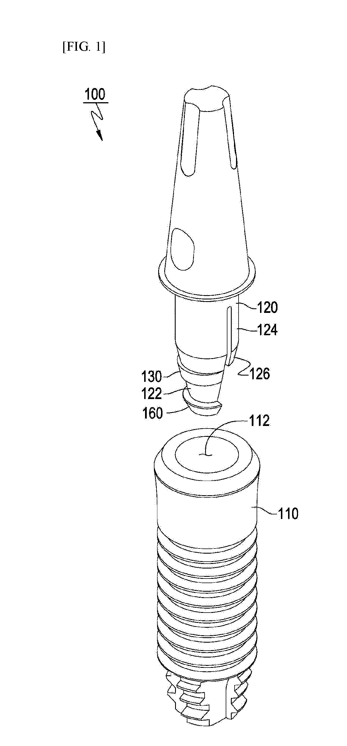
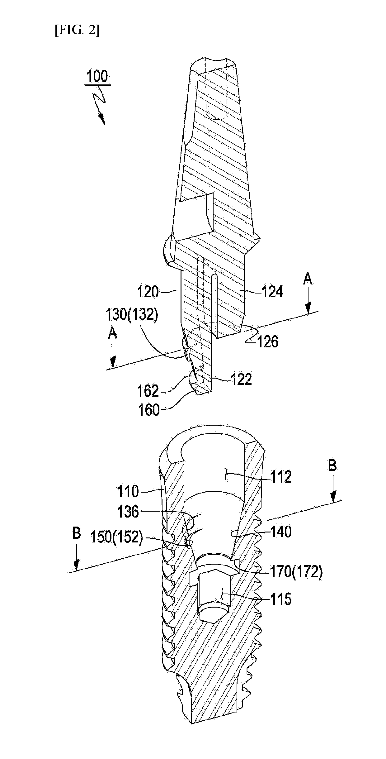
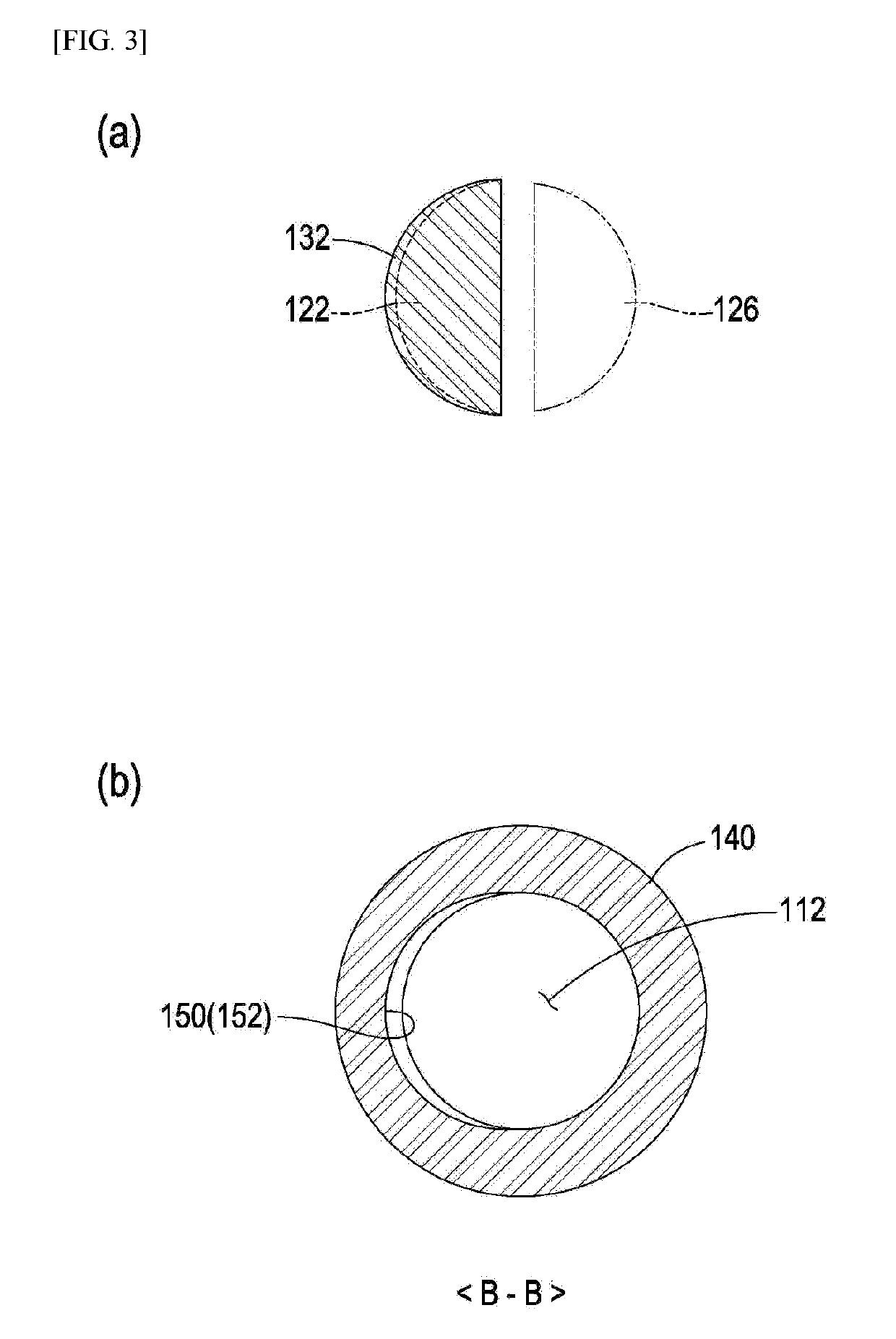
[0045]As illustrated in FIGS. 1 and 2, a dental implant 100 according to the present invention includes a fixture 110 implanted in an alveolar bone (not shown) to form an artificial tooth root, and an abutment 120 comprised of elastic legs 122 and 124. In each of the elastic legs 122 and 124, a top portion thereof is coupled to a prosthesis (e.g. a crown or a denture), and a bottom portion thereof is elastically coupled to an axial hole 112 of the fixture 110.

[0046]The elastic legs 122 and 124 of the abutment 120 include an elastic fastening leg 122 acting to couple the abutment 120 to the fixture 110 using elastic bending in the axial direction and restoring force, and an elastic non-fastening support leg 124 that does not directly participate in the coupling of the abutment 120 to the fixture 110. Although the elastic legs are illustrated herein ...


PUM


Abstract

The present invention provides a dental implant including: a fixture and an abutment including a coupling leg, and the fixture and the abutment are elastically coupled with each other, the dental implant including: a fixture axial hole inner inclined surface in which an inner diameter of an axial hole is gradually and downwardly reduced from a predetermined position of an inner inclined surface of the fixture; a first coupling part formed with a coupling hole at a predetermined position of the fixture; and a first associated coupling part formed with a coupling protrusion complementarily coupled with the first coupling part, wherein when the first associated coupling part is separated from the first coupling part by rotating the abutment, the coupling protrusion upwardly pushes the abutment from the fixture by elastic repulsion with the axial hole inner inclined surface of the fixture, thus the abutment becomes separated from the fixture.

Description

CROSS REFERENCE TO RELATED APPLICATIONS[0001]This application is a 371 application from international patent application PCT / KR2018 / 000695 filed Jan. 15, 2018, and is related to and claims priority from Korea Patent Application No. KR 10-2017-0006426 filed Jan. 13, 2017, which is incorporated herein by reference in its entirety.TECHNICAL FIELD[0002]The present invention relates to a dental implant fixing a dental prosthesis by forming an artificial tooth root that is coupled and implanted in the alveolar bone. More particularly, the present invention relates to a dental implant whereby an abutment is easily separated from a fixture of the dental implant, and vertical occlusal force applied thereto may be efficiently absorbed by improving a coupling structure between the fixture and the abutment.BACKGROUND ART[0003]In dentistry, an implant means an artificial tooth substituting for a lost natural tooth or a dental procedure that is conducted in such a manner that a fixture is implant...

Claims


Application Information

Patent Timeline
Patent Type & Authority Applications(United States)
IPC IPC(8): A61C8/00
CPCA61C8/0057A61C8/0086A61C8/00A61C8/0062A61C8/0056A61C8/0007
Inventor KIM, HYUNG WOO
Owner DENFLEX CO LTD
Why Eureka
Try Eureka