Inkjet printhead with sealed shield plate

a printhead and shield plate technology, applied in the field of printheads, can solve the problems of lcp manifolds with some practical limitations, chip depriming, and easy trapping of labyrinthine ink pathways, and achieve the effects of stable structure, robust printhead structure, and greater flexibility in the choice of materials

Active Publication Date: 2019-10-24
MEMJET TECH LTD
View PDF1 Cites 0 Cited by
  • Summary
  • Abstract
  • Description
  • Claims
  • Application Information

AI Technical Summary

Benefits of technology

[0057]The printhead according to the third aspect employs a suitable metal alloy (e.g. Invar) shim for adhesive bonding of a plurality of printhead chips to the manifold using, for example, an epoxy adhesive applied as a liquid to one or both bonding surfaces. The shim has minimal expansion at high temperatures and provides a stable structure for mounting a plurality of printhead chips to the manifold. This, in turn, provides greater flexibility in the choice of materials for the manifold. The manifold may be comprised of a material which is the same or different than the shim, and may be selected on the basis of stiffness, cost, manufacturability etc. For example, the manifold may be comprised of a material, such as stainless steel, Invar or a polymer. Typically, the manifold is comprised of a same material as the shim.
[0058]The adhesion-promoting surface film layer may be comprised of a coating material selected from the group consisting of: diamond-like carbon (DLC), metal oxide (e.g. alumina, silica, tantala, hafnia etc.), metal nitride (e.g. silicon nitride, chromium nitride etc.), metal (e.g. chromium, stainless steel etc.) and a polymer. The adhesion-promoting surface film layer assists in bonding the printhead chips to the shim with via an adhesive to provide a robust printhead structure. Likewise, shim-to-manifold bonding strength may be improved via the adhesion-promoting surface film layer

Problems solved by technology

However, at high print speeds, the LCP manifold has some practical limitations.
Without a sufficiently large body of ink close to the printhead chips, the chips may become starved of ink under periods of high ink demand and lead to chip de-priming.
Secondly, the labyrinthine ink pathways are susceptible to trapping air bubbles; if an air bubble becomes trapped in the system, the printhead chips will become starved of ink and de-prime.
Whilst LCP is a satisfactory choice of material for A4 printheads, having a CTE similar to silicon, it typically lacks the required rigidity to manufacture longer printheads (e.g. A3 printheads).
However, flex PCBs are expensive and add significantly to manufacturing costs.
Moreover, bending of a flex PCB through a tight angle places strain on the PCB and limits the components that may be incorporated thereon.
However, a problem with stacking printheads in this manner is that precise registration of the printheads is required when printheads are replaced by the user.
Further, there are high demands on media feed mechanisms, which must maintain alignment of the print media with the printheads through a relatively long print zone.

Method used


Image

  • Inkjet printhead with sealed shield plate
  • Inkjet printhead with sealed shield plate
  • Inkjet printhead with sealed shield plate

Examples


Embodiment Construction

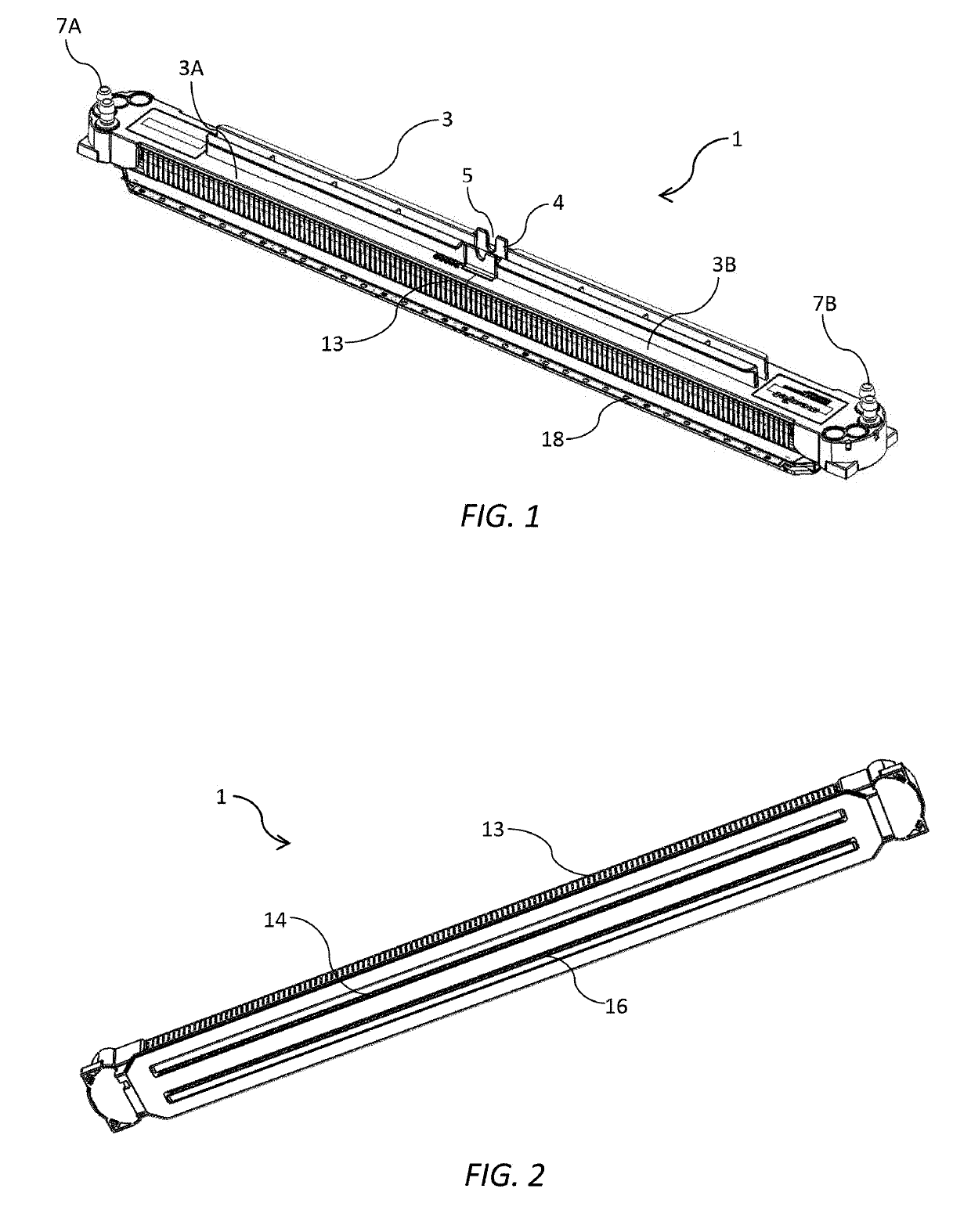
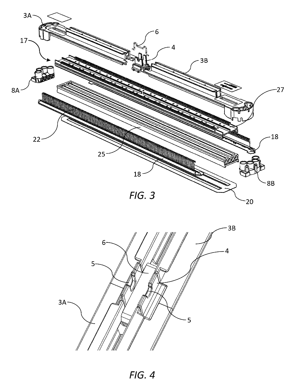
[0190]Referring to FIGS. 1 to 4, there is shown an inkjet printhead 1 in the form of a replaceable printhead cartridge for user insertion in a printer (not shown). The printhead 1 comprises an elongate molded plastics casing 3 having a first casing part 3A and a second casing part 3B positioned at either side of a central locator 4. The central locator 4 has an alignment notch 5 for positioning the printhead cartridge 1 relative to a print module, such as a print module of the type described in US2017 / 0313061, the contents of which are incorporated herein by reference. The first and second casing parts 3A and 3B are biased towards each other and the central locator 4 by means of a spring clip 6 engaged between the first and second casing parts (see FIG. 4). The two-part casing 3 in combination with the spring clip 6 enables the casing to expand longitudinally, at least to some extent, to accommodate a degree of longitudinal expansion in a main body 17 of the printhead 1. This arrang...


PUM


Abstract

An inkjet printhead includes: a support structure having a plurality of printhead chips mounted thereto; and a shield plate bonded to the support structure, the shield plate having a slot aligned with the printhead chips, the slot having a perimeter edge. A sealant is disposed on all exposed portions of the support structure adjacent the perimeter edge of each slot.

Description

CROSS-REFERENCE TO RELATED APPLICATIONS[0001]The present application is a continuation-in-part of U.S. application Ser. No. 16 / 051,319 filed Jul. 31, 2018, which is a continuation-in-part of U.S. application Ser. No. 15 / 888,852 filed Feb. 5, 2018, which claims the benefit of priority under 35 U.S.C. § 119(e) of U.S. Provisional Application No. 62 / 455,346, filed Feb. 6, 2017, the contents of each of which are hereby incorporated by reference in their entirety for all purposes.FIELD OF THE INVENTION[0002]This invention relates to an inkjet printhead. It has been developed primarily to provide a robust full-color printhead suitable for high-speed pagewide printing.BACKGROUND OF THE INVENTION[0003]The Applicant has developed a range of Memjet® inkjet printers as described in, for example, WO2011 / 143700, WO2011 / 143699 and WO2009 / 089567, the contents of which are herein incorporated by reference. Memjet® printers employ one or more stationary inkjet printheads in combination with a feed m...

Claims


Application Information

Patent Timeline
Patent Type & Authority Applications(United States)
IPC IPC(8): B41J2/14B41J2/155
CPCB41J2/155B41J2/1433B41J2/14B41J2002/14419B41J2002/14362B41J2202/08
Inventor PEREZ, ELMER DIMACULANGANCHIN, NICHOLASWANG, MIAOTAN, SEE-HUATTHELANDER, JASONBURKE, DAVIDTHOMAS, ANDREWRAJARATNAM, MAHES
Owner MEMJET TECH LTD
Why Eureka
Try Eureka