
High performance stacked connector

a technology of stacked connectors and connectors, applied in the direction of fixed connections, coupling device connections, instruments, etc., can solve the problems of generating a lot of heat, consuming a lot of power of the transceiver for converting optical signals to electrical signals, and temperature around electronic, optical, or other components to exceed the rated operating temperature, so as to achieve the effect of dissipating hea

Active Publication Date: 2019-10-24
AMPHENOL CORP
View PDF4 Cites 8 Cited by
  • Summary
  • Abstract
  • Description
  • Claims
  • Application Information

AI Technical Summary

Benefits of technology

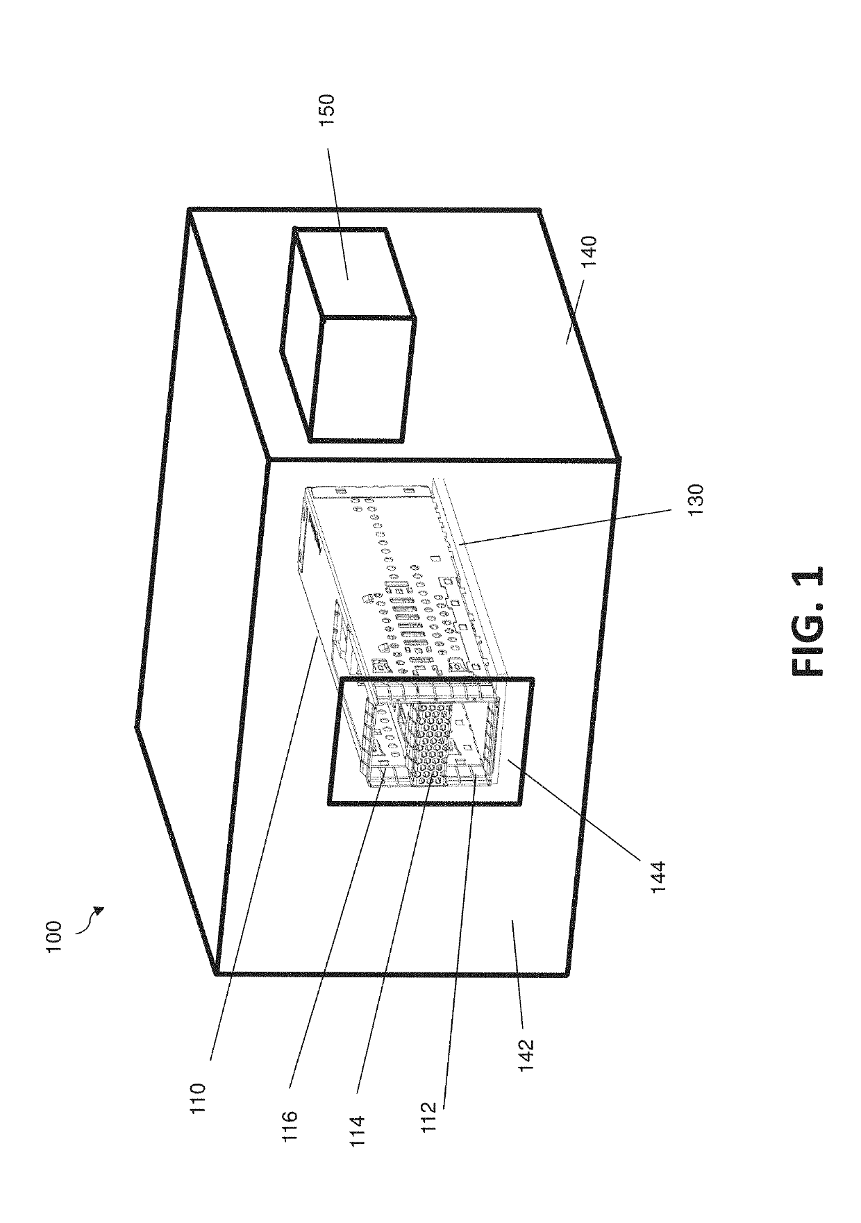
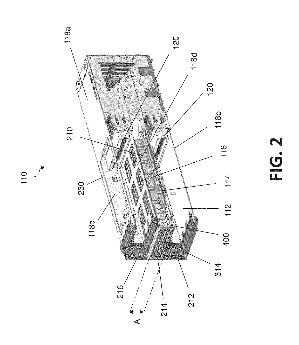
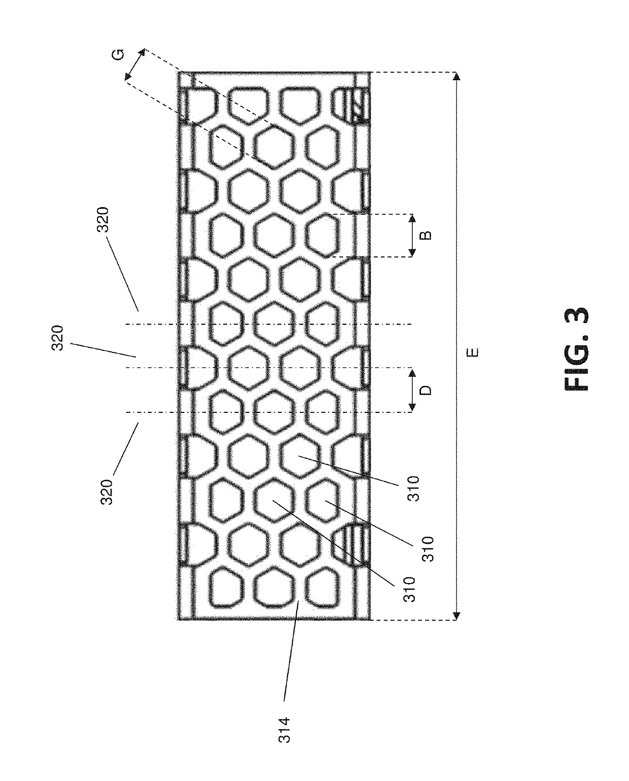
The invention is a cage for an electrical connector that includes a first channel and a second channel with a face that has a plurality of holes. The holes are arranged in a plurality of lines that are offset from each other in a first direction. The cage also includes a printed circuit board and a connector mounted on the circuit board, which is enclosed by the cage. The cage is designed to dissipate heat from the transceivers in a way that prevents the temperature rise of the transceivers relative to an off state of the transceivers in an ambient environment of 25 degrees C. The invention also includes an electronic system with a stacked cage and a fan within the enclosure that flows air through the face of the second channel to dissipate heat from the transceivers in the first and third channels. The technical effect of the invention is to improve the heat dissipation efficiency of the electronic system.

Problems solved by technology

A transceiver for converting optical signals to electrical signals may consume a lot of power, and therefore generate a lot of heat.
Transceivers that process more signals, such as transceivers made according to a QSFP-DD standard, may consume up to 15 W. Large amounts of heat may cause the temperature around electronic, optical, or other components to exceed the rated operating temperature, contributing to errors during operation or reducing the lifetime of the components.

Method used


Image

  • High performance stacked connector
  • High performance stacked connector
  • High performance stacked connector

Examples


Embodiment Construction

[0015]The present disclosure is directed to an electronic connection system, which may be compliant with QSFP standards in at least one aspect. The inventors have recognized and appreciated designs that enable an increased density of I / O connections. The inventors have recognized and appreciated that an increased density of I / O connections may require improved heat dissipation from I / O connectors. Increased density may arise from transceivers that process more signals in the same space, such as may arise in transceivers compliant with the QSFP-DD standard. Additionally, increased density may result from “stacking” connectors, which results in transceivers one above the other with only a small space between them. The inventors have further recognized and appreciated techniques to provide improved heat dissipation even for stacked connectors.

[0016]Those techniques may entail forming holes in a surface of a cage designed to enclose a transceiver. The holes may be formed in a pattern to...


PUM


Abstract

A cage for a stacked I / O connector that provides heat dissipation sufficient to support operation of QSFP-DD transceivers with a conventionally-sized cooling fan. The cage includes a second channel, between a first and a third channel that are sized and positioned adjacent ports of a connector so as to receive two transceivers. A face of the second channel may have a pattern of openings that enables a high airflow yet blocks electromagnetic radiation that would otherwise contribute to EMI. An element, adjacent the channel that similarly has a pattern of holes enabling high airflow, may further block EMI.

Description

BACKGROUND[0001]An electronic system may include two or more electronic devices connected with a cable. The devices may have input / output (I / O) connectors for connecting with plug connectors terminating the ends of the cable. The cable may be constructed to carry electrical or optical signals. For transmitting optical signals, a transceiver is provided at one end of the cable for converting the optical signals to electrical signals.[0002]The plugs and I / O connectors may be constructed according to standards that enable components from different manufacturers to mate. For example, the Quad Small Form-factor Pluggable (QSFP) standard defines a compact, hot-pluggable transceiver used for data communications applications. The form factor and electrical interface are specified by a multi-source agreement (MSA) under the auspices of the Small Form Factor (SFF) Committee. Components made according to the QSFP standard is widely used to interface networking hardware (such as servers and swi...

Claims


Application Information

Patent Timeline
IPC IPC(8): H01R13/514H05K7/20H04B10/40H04B10/80H01R13/6581H01R12/53
CPCH01R13/514H04B10/801H04B10/40H05K7/20154H01R12/53H01R13/6581G02B6/4246G02B6/4261G02B6/4277G02B6/4269G02B6/4268
Inventor CHEN, XINGYE
Owner AMPHENOL CORP
Learn More