Supercharge Your Innovation With Domain-Expert AI Agents!

Vibration rectification error correction circuit, physical quantity sensor module, structure monitoring device, and correction value adjustment method of vibration rectification error correction circuit

a technology of vibration rectification error and correction value, which is applied in the direction of acceleration measurement using interia forces, speed measurement using gyroscopic effects, instruments, etc., can solve the problems of rectification error, lowering measurement accuracy, and distortion of output signal with respect to the applied signal

Active Publication Date: 2019-10-31
SEIKO EPSON CORP
View PDF4 Cites 6 Cited by
  • Summary
  • Abstract
  • Description
  • Claims
  • Application Information

AI Technical Summary

Benefits of technology

The present disclosure provides a correction value adjustment method for a vibration rectification error correction circuit. The method includes a first correction circuit that obtains a digital value based on a sensor element and corrects a vibration rectification error of the digital value by a correction function based on a product of values obtained by biasing the digital value, a frequency delta sigma modulation circuit for generating a frequency delta sigma modulation signal, and a second correction circuit that corrects the vibration rectification error based on a filter characteristic of a first filter circuit and a filter characteristic of a second filter circuit. The method allows for adjusting a correction value of the correction function and filter characteristics of the first and second filter circuits simultaneously. The technical effect of the present disclosure is to provide a more efficient and accurate method for correcting vibration rectification errors in a sensor signal.

Problems solved by technology

On the other hand, in a device or system in which the output signal output from the sensor element is nonlinear with respect to the applied signal applied to the sensor element, distortion occurs in the output signal with respect to the applied signal.
The vibration rectification error is an error signal generated by the device or system having nonlinearity and is not originally contained in the applied signal.
Such a rectification error signal may affect performance of a processing system or an application system coupled to a rear stage of the device or system.
For example, in a measurement apparatus using a sensor having nonlinearity, measurement accuracy may be lowered due to the vibration rectification error due to the nonlinearity.
However, since the vibration rectification error is nonlinear, there is a possibility that a correction computation for correcting the vibration rectification error becomes complicated and a computation load for correcting the vibration rectification error increases.

Method used


Image

  • Vibration rectification error correction circuit, physical quantity sensor module, structure monitoring device, and correction value adjustment method of vibration rectification error correction circuit
  • Vibration rectification error correction circuit, physical quantity sensor module, structure monitoring device, and correction value adjustment method of vibration rectification error correction circuit
  • Vibration rectification error correction circuit, physical quantity sensor module, structure monitoring device, and correction value adjustment method of vibration rectification error correction circuit

Examples


first embodiment

1.1 First Embodiment

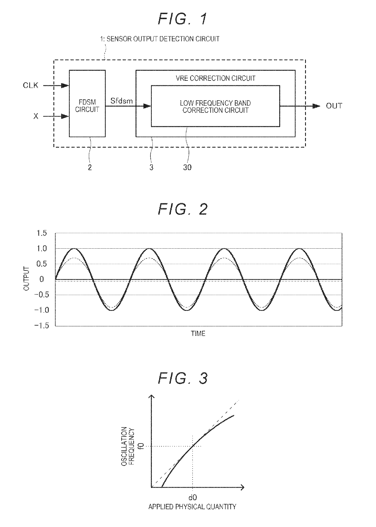
[0038]FIG. 1 is a block diagram illustrating functional blocks of a sensor output detection circuit 1 of a first embodiment. As illustrated in FIG. 1, the sensor output detection circuit 1 of the first embodiment includes a frequency delta-sigma modulator (FDSM) circuit 2 and a vibration rectification error (VRE) correction circuit 3.

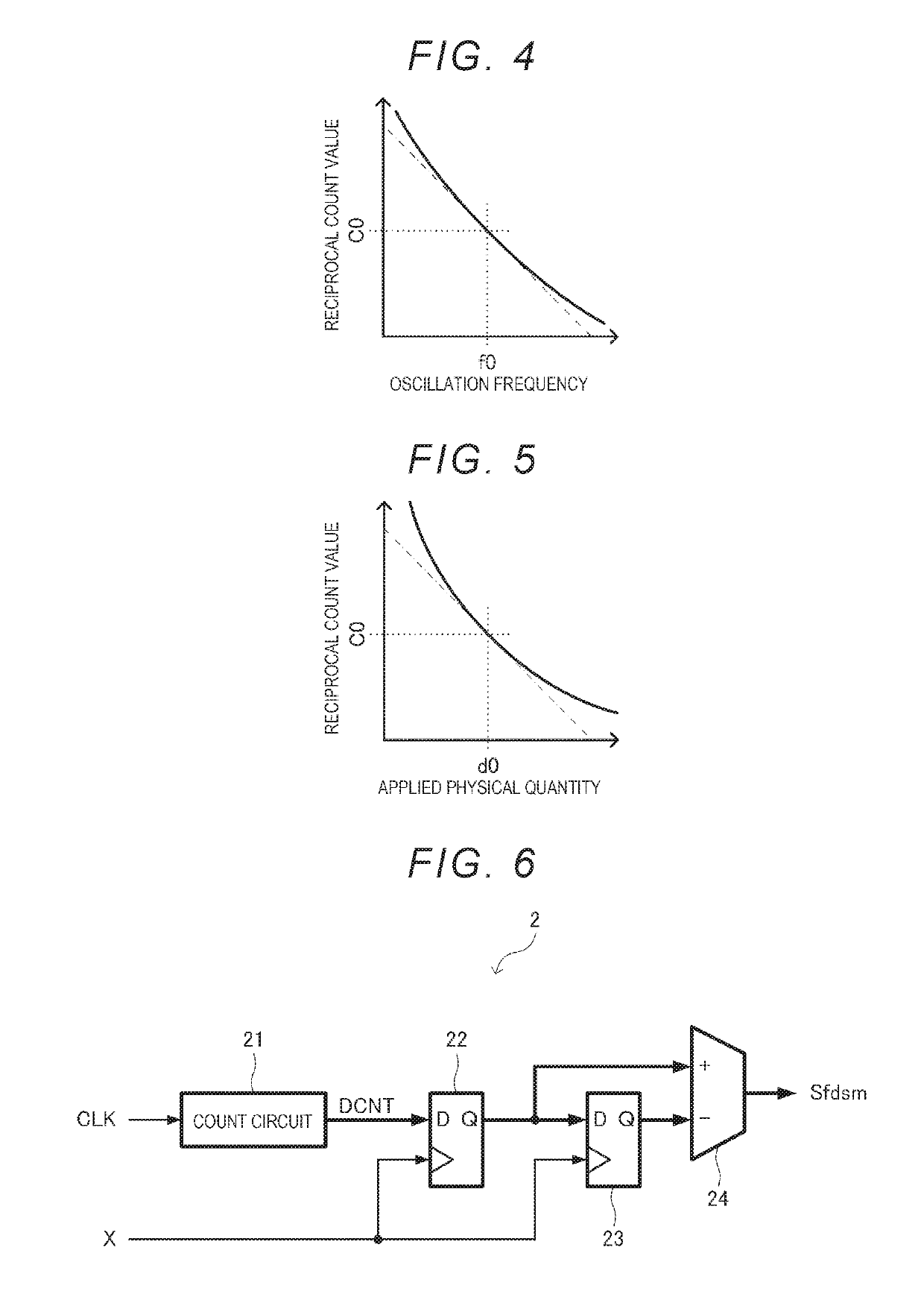
[0039]A reference signal CLK and a signal X to be measured output from a sensor element configured to measure the physical quantity as illustrated in FIG. 18, for example, are input to the sensor output detection circuit 1. The sensor output detection circuit 1 measures a frequency ratio between the signal X to be measured and the reference signal CLK by a reciprocal count method and outputs the frequency ratio as a reciprocal count output signal OUT. In the following description, although description is made on the assumption that the signal X to be measured output from the sensor element is directly input to the sensor output detec...

second embodiment

1.2. Second Embodiment

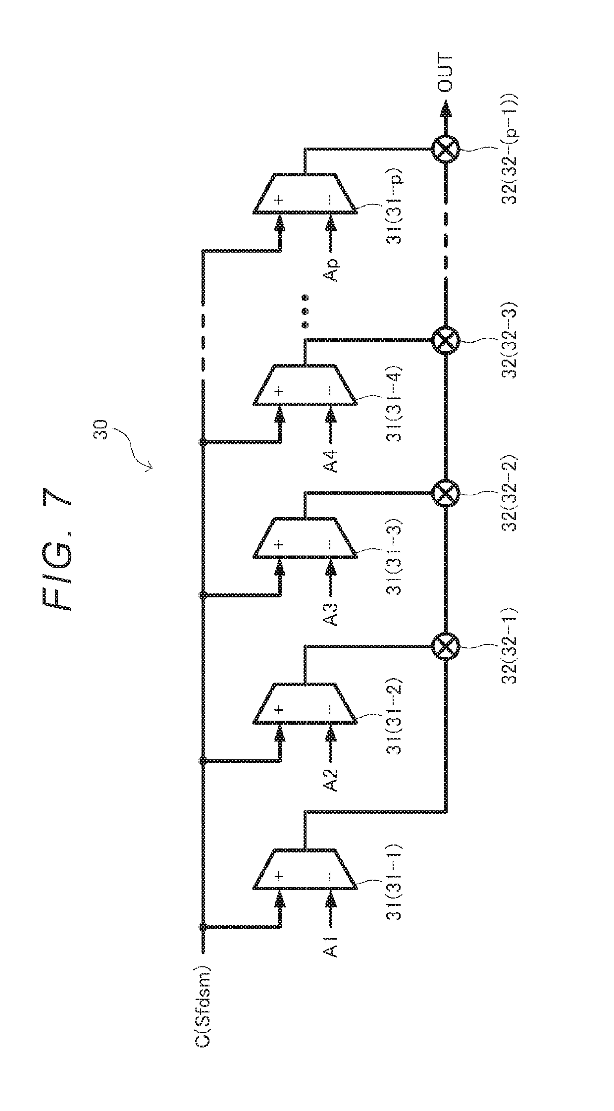
[0071]Next, the sensor output detection circuit 1 of the second embodiment will be described. The sensor output detection circuit 1 of the second embodiment is different from the first embodiment in that the VRE correction function included in the low frequency band correction circuit 30 is a quadratic polynomial expressed in the factorization form and is indicated by a power of factor. In describing the sensor output detection circuit 1 of the second embodiment, the same reference numerals are given to the same configurations as those of the first embodiment, and the description thereof will be omitted.

[0072]The VRE is a function of the oscillation frequency output from the sensor element due to the input applied physical quantity, and if the oscillation frequency due to the applied physical quantity is constant, the magnitude of VRE is proportional to the square of amplitude of the output signal of the sensor element due to the applied physical quantity. That...


PUM


Abstract

A vibration rectification error correction circuit includes a first correction circuit that obtains a digital value based on a signal to be measured output from a sensor element configured to measure a physical quantity and corrects a vibration rectification error of the digital value by a correction function based on a product of values obtained by biasing the digital value.

Description

[0001]The present application is based on and claims priority from JP Application Serial Number 2018-086187, filed Apr. 27, 2018, the disclosure of which is hereby incorporated by reference herein in its entirety.BACKGROUND1. Technical Field[0002]The present disclosure relates to a vibration rectification error correction circuit, a physical quantity sensor module, a structure monitoring device, and a correction value adjustment method of the vibration rectification error correction circuit.2. Related Art[0003]In a device or system including a sensor element, in a case in which linearity of an output signal output from the sensor element is good with respect to an applied signal applied to the sensor element, an average value of the output signal becomes zero when the applied signal is sine wave vibration. On the other hand, in a device or system in which the output signal output from the sensor element is nonlinear with respect to the applied signal applied to the sensor element, d...

Claims


Application Information

Patent Timeline
Patent Type & Authority Applications(United States)
IPC IPC(8): G01C19/5614G01P15/125G01H17/00G01C19/5719G01P15/13
CPCG01P15/125G01C19/5719G01P2015/0822G01H17/00G01P15/132G01C19/5614G01D18/00G01P21/00G01H3/005G01P15/10G01C25/005
Inventor TODOROKIHARA, MASAYOSHISATO, KENTA
Owner SEIKO EPSON CORP
Features
  • R&D
  • Intellectual Property
  • Life Sciences
  • Materials
  • Tech Scout
  • Unparalleled Data Quality
  • Higher Quality Content
  • 60% Fewer Hallucinations
Learn More