Antenna module

a technology of antenna module and antenna, applied in the field of antenna module, can solve the problems of discontinuous impedance of a load connected to an antenna, unstable electrical connection, and affecting and achieve the effect of reducing the efficiency of the antenna and stable electrical connection

Active Publication Date: 2019-10-31
MURATA MFG CO LTD
View PDF0 Cites 3 Cited by
  • Summary
  • Abstract
  • Description
  • Claims
  • Application Information

AI Technical Summary

Benefits of technology

[0006]In the case where a plurality of the upper green sheets are stacked such that the upper green sheets are curved, an upper green sheet disposed on a lower side and an upper green sheet disposed on an upper side have different curvatures from each other. Therefore, in the case where a conductor pattern provided on the upper green sheet disposed on the lower side and a conductor pattern provided on the upper green sheet disposed on the upper side are joined to each other by a via conductor provided in the upper green sheets, the via conductor will be diagonally inclined and the electrical connections will be unstable. Furthermore, in the case where lands having a large area are formed at the places where the via conductor is connected in order to secure stable electrical connections, the impedance of a load connected to an antenna will become discontinuous and the efficiency of the antenna will decrease.

Problems solved by technology

Therefore, in the case where a conductor pattern provided on the upper green sheet disposed on the lower side and a conductor pattern provided on the upper green sheet disposed on the upper side are joined to each other by a via conductor provided in the upper green sheets, the via conductor will be diagonally inclined and the electrical connections will be unstable.
Furthermore, in the case where lands having a large area are formed at the places where the via conductor is connected in order to secure stable electrical connections, the impedance of a load connected to an antenna will become discontinuous and the efficiency of the antenna will decrease.

Method used


Image

  • Antenna module
  • Antenna module
  • Antenna module

Examples


embodiment 1

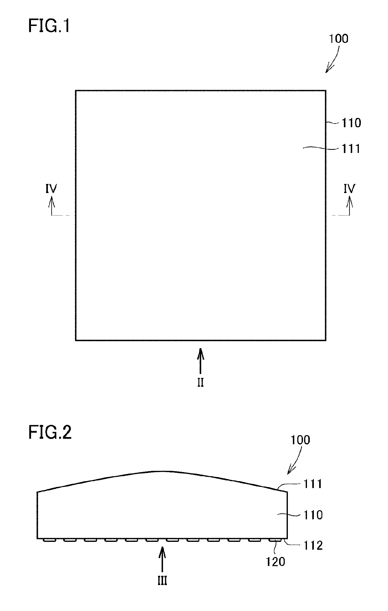
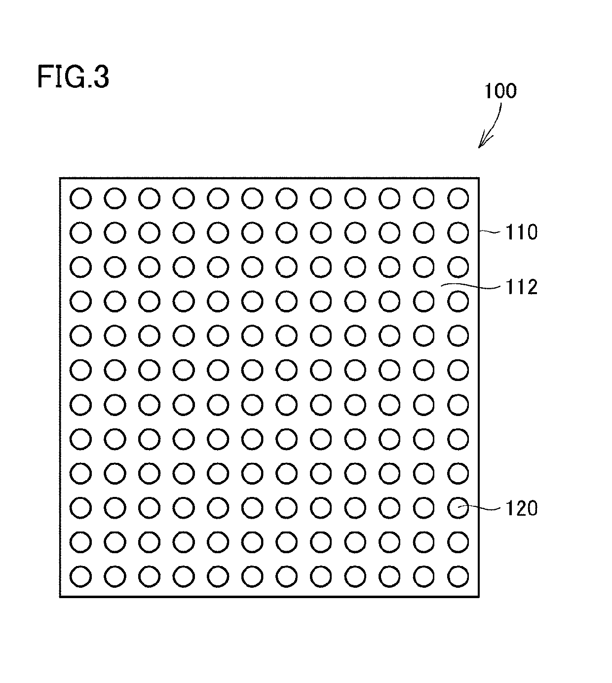
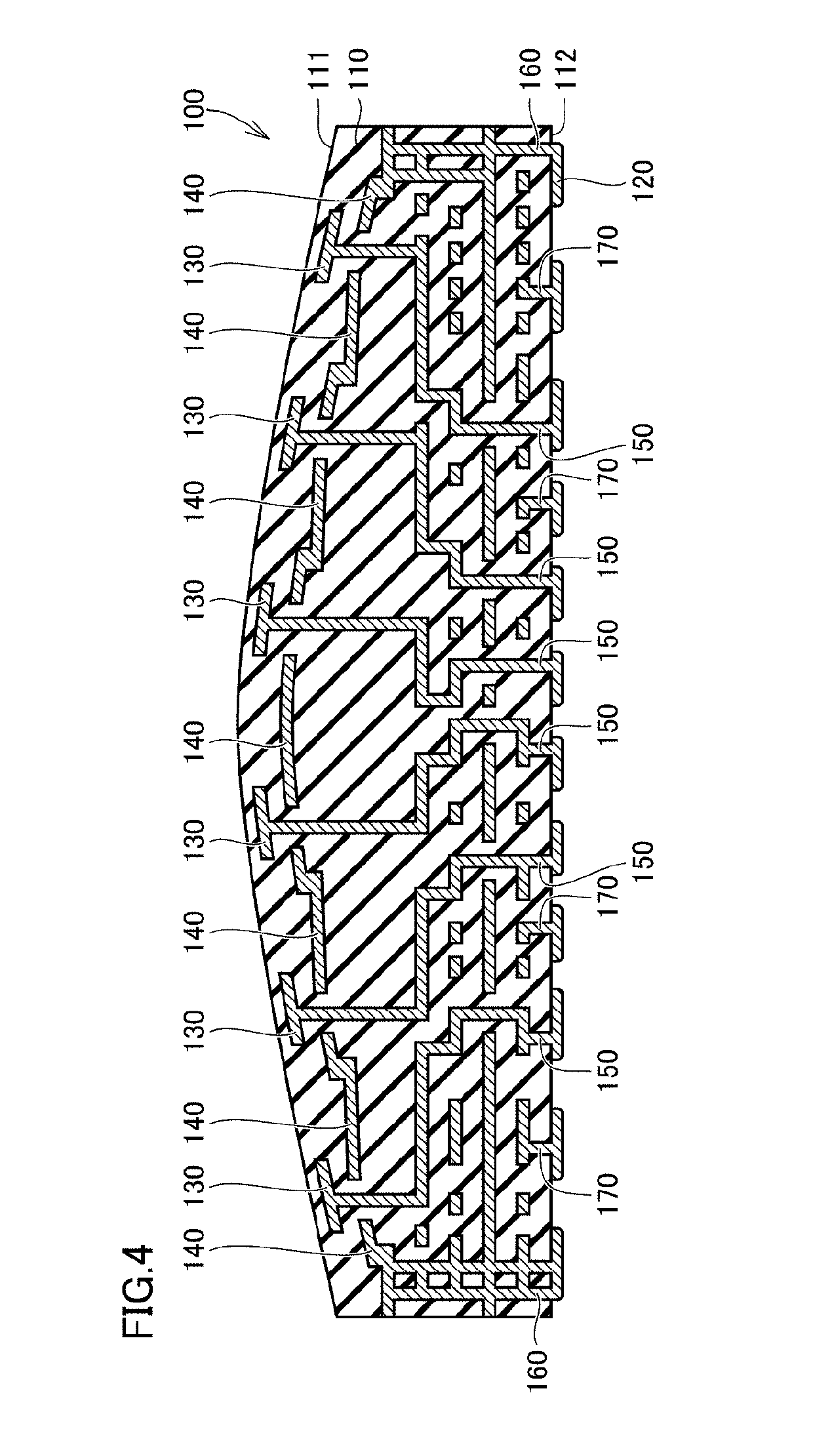
[0032]FIG. 1 is a plan view illustrating the exterior of an antenna module according to embodiment 1 of the present disclosure. FIG. 2 is a side view in which the antenna module in FIG. 1 is viewed in the direction of arrow II. FIG. 3 is a rear view in which the antenna module in FIG. 2 is viewed in the direction of arrow III. FIG. 4 is a sectional view in which the antenna module in FIG. 1 is viewed in the direction of the arrows of line IV-IV.

[0033]As illustrated in FIGS. 1 to 4, an antenna module 100 according to embodiment 1 of the present disclosure includes: a base part 110; a plurality of connection terminals 120 that are for external connections; a plurality of antenna elements 130; a plurality of connection wiring lines 150; and a ground wiring line 140. The antenna module 100 further includes a plurality of connection wiring lines 160 and a plurality of connection wiring lines 170. The antenna module 100 according to this embodiment functions as a conformal array antenna.

[...

embodiment 2

[0077]Hereafter, an antenna module according to embodiment 2 of the present disclosure will be described while referring to the drawings. An antenna module 200 according to embodiment 2 of the present disclosure mainly differs from the antenna module 100 according to embodiment 1 in that the antenna module 200 further includes a cover layer and radiation electrodes provided on the cover layer and in that electronic components are mounted therein, and therefore the description of the configurations that are the same as in the antenna module 100 according to embodiment 1 will not be repeated.

[0078]FIG. 11 is a plan view illustrating the exterior of the antenna module according to embodiment 2 of the present disclosure. FIG. 12 is a side view in which the antenna module in FIG. 11 is viewed in the direction of arrow XII. FIG. 13 is a rear view in which the antenna module in FIG. 12 is viewed in the direction of arrow XIII. FIG. 14 is a sectional view in which the antenna module in FIG....


PUM


Abstract

A base part (110) has one main surface (111) that is spherically curved so as to protrude outward and another main surface (112) that is flat. A plurality of antenna elements (130) are provided along the one main surface (111) inside the base part (110). A plurality of connection wiring lines (150) connect the plurality of connection terminals (120) and the plurality of antenna elements (130) to each other. A part of each of the plurality of connection wiring lines (150) disposed in a region where a ground wiring line (140) is provided extends in a direction perpendicular to the other main surface (112) when viewed in a direction perpendicular to the other main surface (112).

Description

BACKGROUND OF THE DISCLOSURE[0001]This is a continuation of International Application No. PCT / JP2017 / 045087 filed on Dec. 15, 2017 which claims priority from Japanese Patent Application No. 2017-003384 filed on Jan. 12, 2017. The contents of these applications are incorporated herein by reference in their entireties.FIELD OF THE DISCLOSURE[0002]The present disclosure relates to an antenna module and in particular relates to an antenna module that includes a multilayer substrate.DESCRIPTION OF THE RELATED ART[0003]Japanese Unexamined Patent Application Publication No. 9-183110 (Patent Document 1) is a prior art document that discloses the configuration of a curved surface multilayer ceramic sheet that is formed by stacking ceramic green sheets and has a semicircular vertical cross section.[0004]The curved surface multilayer ceramic sheet disclosed in Patent Document 1 includes a lower green sheet having a semicircular vertical cross section, an upper green sheet that is provided on t...

Claims


Application Information

Patent Timeline
Patent Type & Authority Applications(United States)
IPC IPC(8): H01Q21/06H01Q1/48H01Q1/22
CPCH01Q1/22H01Q1/48H01Q21/065H05K3/46H01Q21/20H01Q1/2283H01L2224/16227H01L2924/19105H01L2223/6677
Inventor KAMIO, SHIGEYUKIAMACHI, NOBUMITSU
Owner MURATA MFG CO LTD
Why Eureka
Try Eureka