
Method And System For Second Pass Confirmation Of Detected Cardiac Arrhythmic Patterns

a second-pass confirmation and cardiac arrhythmia technology, applied in the field of implantable medical devices, can solve the problems of providing false positive af detection, existing af detection algorithms may experience undue false positives, and inefficiently, and achieve the effect of enhancing sinus features and enhancing sinus features

Active Publication Date: 2019-11-07
PACESETTER INC
View PDF1 Cites 5 Cited by
  • Summary
  • Abstract
  • Description
  • Claims
  • Application Information

AI Technical Summary

Benefits of technology

The patent text describes a method for improving the detection of electrical activity in the heart to diagnose and treat conditions like atrial fibrillation. The method involves analyzing data from a cardiac device to look for specific features that indicate an abnormal heart rhythm. By using a feature enhancement function, the method can identify potential abnormalities and reduce the likelihood of false detections. Additionally, the method can detect premature ventricular contractions and use them to confirm or refute the presence of atrial fibrillation. Overall, this technique can improve the accuracy and reliability of diagnostic cardiac devices.

Problems solved by technology

Alternatively, impulse propagation through the AV node may be very limited due to AV node refractoriness so that atrial fibrillation can be sustained indefinitely, as the ventricles continue to drive circulation, albit inefficiently.
However, these algorithms may provide false positive AF detections when AF did not necessarily exist.
Further, existing AF detection algorithms may experience undue false positives in connection with frequent premature ventricular contraction (PVC).
Existing AF algorithms may not exhibit sufficient positive predictive value (PPV) of AF episode detection and duration (burden).

Method used


Image

  • Method And System For Second Pass Confirmation Of Detected Cardiac Arrhythmic Patterns
  • Method And System For Second Pass Confirmation Of Detected Cardiac Arrhythmic Patterns
  • Method And System For Second Pass Confirmation Of Detected Cardiac Arrhythmic Patterns

Examples


Embodiment Construction

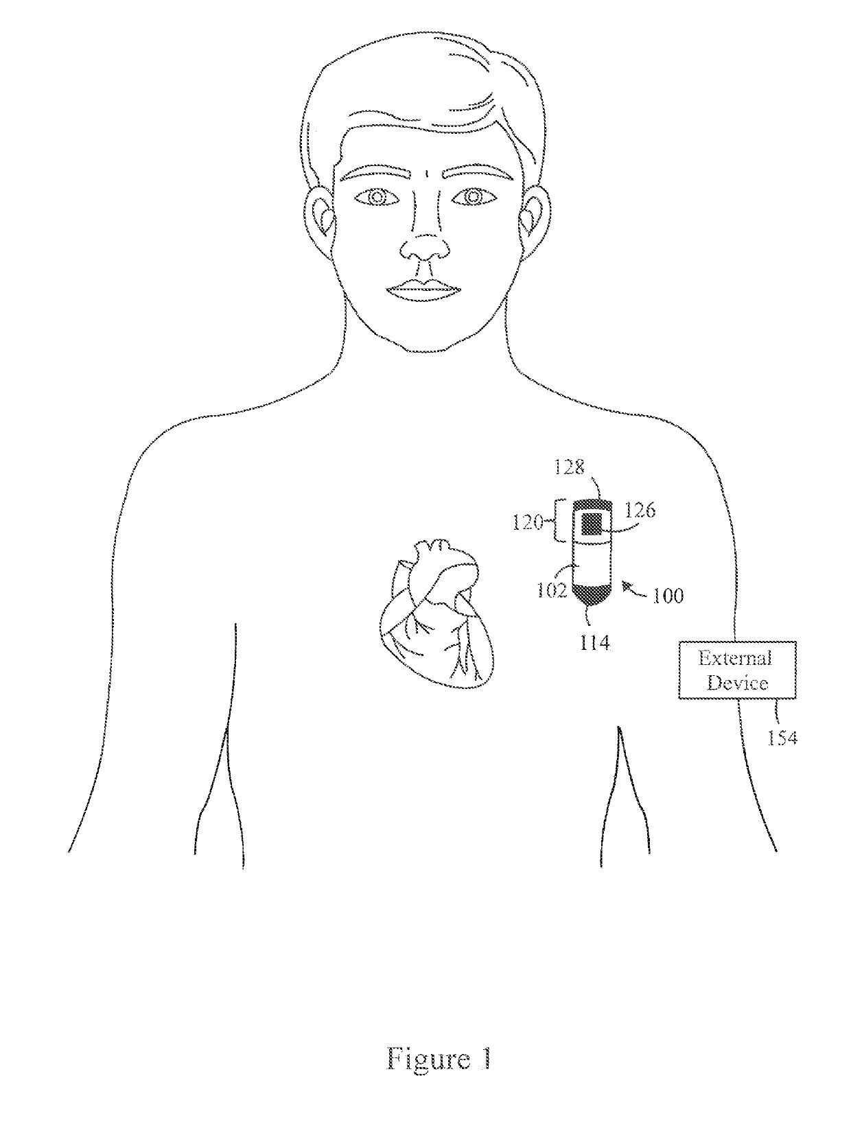
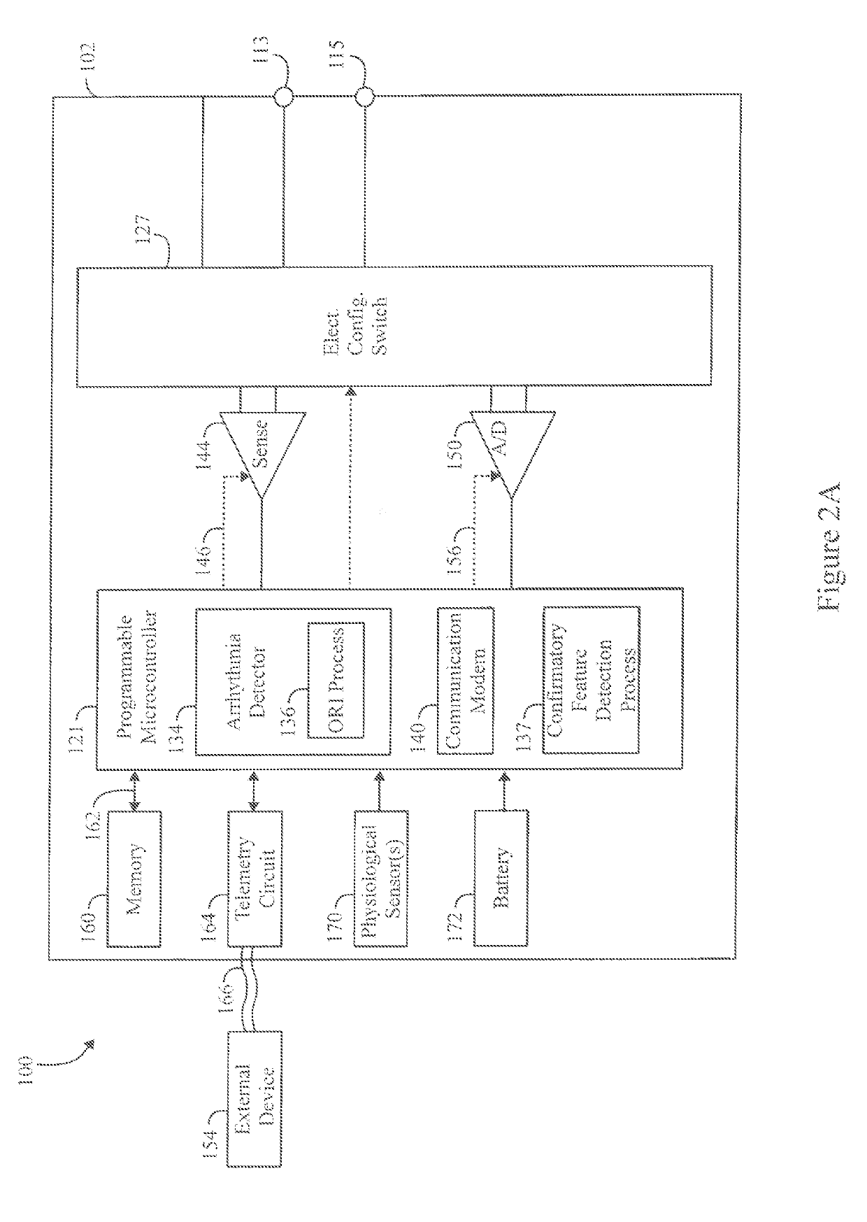
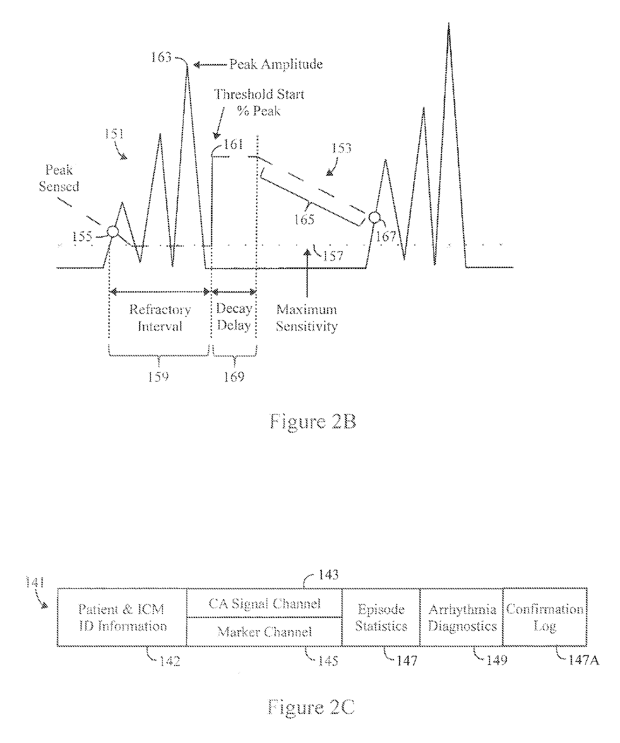
[0043]FIG. 1 illustrates an implantable cardiac monitoring device (ICM) 100 intended for subcutaneous implantation at a site near the heart. The ICM 100 includes a pair of spaced-apart sense electrodes 114, 126 positioned with respect to a housing 102. The sense electrodes 114, 126 provide for detection of far field electrogram signals. Numerous configurations of electrode arrangements are possible. For example, the electrode 114 may be located on a distal end of the ICM 100, while the electrode 126 is located on a proximal side of the ICM 100. Additionally or alternatively, electrodes 126 may be located on opposite sides of the ICM 100, opposite ends or elsewhere. The distal electrode 114 may be formed as part of the housing 102, for example, by coating all but a portion of the housing with a nonconductive material such that the uncoated portion forms the electrode 114. In this case, the electrode 126 may be electrically isolated from the housing 114 electrode by placing it on a co...


PUM


Abstract

A computer implemented method and system for confirming a device documented arrhythmia in cardiac activity are provided. The method is under control of one or more processors configured with executable instructions. The method obtains a cardiac activity (CA) data set that includes CA signals for a series of cardiac events and includes device documented (DD) markers within the series of cardiac events. The device documented markers are indicative of atrial fibrillation (AF) detected by the ICM utilizing an on-board R-R interval irregularity (ORI) process to analyze the CA signals. The method applies a feature enhancement function to the CA signals to form modified CA signals with enhanced sinus features and analyzes the enhanced sinus features in the modified CA signals. The method utilized a confirmatory feature detection process to identify false AF detection by the ORI process. The method records a result of the analysis identifying false AF detection by the ORI process.

Description

FIELD OF THE INVENTION[0001]Embodiments herein relate generally to implantable medical devices, and more particularly to detection and discrimination of arrhythmia patterns.RELATED APPLICATIONS[0002]The following applications relate to and are filed concurrently on the same day as the present application, and are expressly incorporated herein by reference in their entireties (hereafter referred to as “Co-Pending Related Applications”):[0003]U.S. patent application Ser. No. ______, titled “METHOD AND SYSTEM TO DETECT R-WAVES IN CARDIAC ARRHYTHMIC PATTERNS” (Docket No.13211USO1)[0004]U.S. patent application Ser. No. ______, titled “METHOD AND SYSTEM TO DETECT P-WAVES IN CARDIAC ARRHYTHMIC PATTERNS” (Docket No. 13257U1),[0005]U.S. patent application Ser. No. ______, titled “METHOD AND SYSTEM TO DETECT PREMATURE VENTRICULAR CONTRACTIONS IN CARDIAC ACTIVITY SIGNALS” (Docket No, 13245USO1), and[0006]U.S. patent application Ser. No. ______, titled “METHOD AND SYSTEM TO DETECT NOISE IN CARD...

Claims


Application Information

Patent Timeline
Patent Type & Authority Applications(United States)
IPC IPC(8): A61B5/04A61B5/046A61B5/0456A61B5/042A61B5/352A61B5/361
CPCA61B5/04012A61B5/0456A61B5/042A61B5/046A61N1/3702G16H50/30G16H40/63G16H50/20G16H50/70G16H20/40A61B5/7203G06F2218/16A61B5/316A61B5/283A61B5/352A61B5/361
Inventor QU, FUJIANGILL, JONGMALHOTRA, NEHAROSENBERG, STUARTBORNZIN, GENE A.DAWOUD, FADY
Owner PACESETTER INC
Learn More