

An alignment tool for aligning bores in structural members
- Summary
- Abstract
- Description
- Claims
- Application Information
AI Technical Summary
Benefits of technology
Problems solved by technology
Method used
Image


Examples
Embodiment Construction
[0005]It is an object of embodiments of the invention to provide an alignment tool for aligning a bore extending through a first structural member with a bore extending through a second structural member, which allows wear on inner surfaces of the bores to be reduced as compared to prior art alignment tools.
[0006]It is a further object of embodiments of the invention to provide an alignment tool for aligning a bore extending through a first structural member with a bore extending through a second structural member, which allows the risk of damage to inner surfaces of the bores to be reduced as compared to prior art alignment tools.
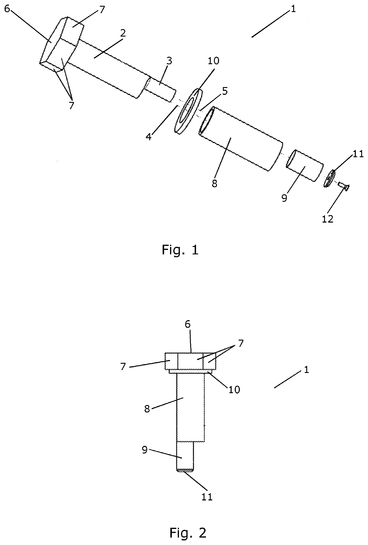
[0007]The invention provides an alignment tool for aligning a bore extending through a first structural member with a bore extending through a second structural member, the alignment tool comprising:[0008]a first shaft portion having a cylindrical or cylindrical like configuration defining a first cylinder axis, a first diameter and a first surface,[0009]a...
PUM
 Abstract
Description
Claims
Application Information