Heat exchanger unit and air conditioner using the same

Pending Publication Date: 2019-11-14
DAIKIN IND LTD
View PDF0 Cites 0 Cited by
  • Summary
  • Abstract
  • Description
  • Claims
  • Application Information

AI Technical Summary

Benefits of technology

The heat exchanger unit in the air conditioner allows for more efficient heat exchange by setting the number of paths that pass through the rows to one or more, and also reducing the influence of a particular row that improves heat exchange performance for a unidirectional air flow. This results in less variation in heat exchange performance when the air flow direction is reversed.

Problems solved by technology

Therefore, the top-blow arrangement and the bottom-blow arrangement do not easily realize the same heat exchange performance.

Method used


Image

  • Heat exchanger unit and air conditioner using the same
  • Heat exchanger unit and air conditioner using the same
  • Heat exchanger unit and air conditioner using the same

Examples


Embodiment Construction

[0032]Embodiments of the present invention are described below with reference to the drawings. The embodiments below are examples of the present invention and do not limit the technical scope of the present invention.[0033](1) Structure of Air Conditioner

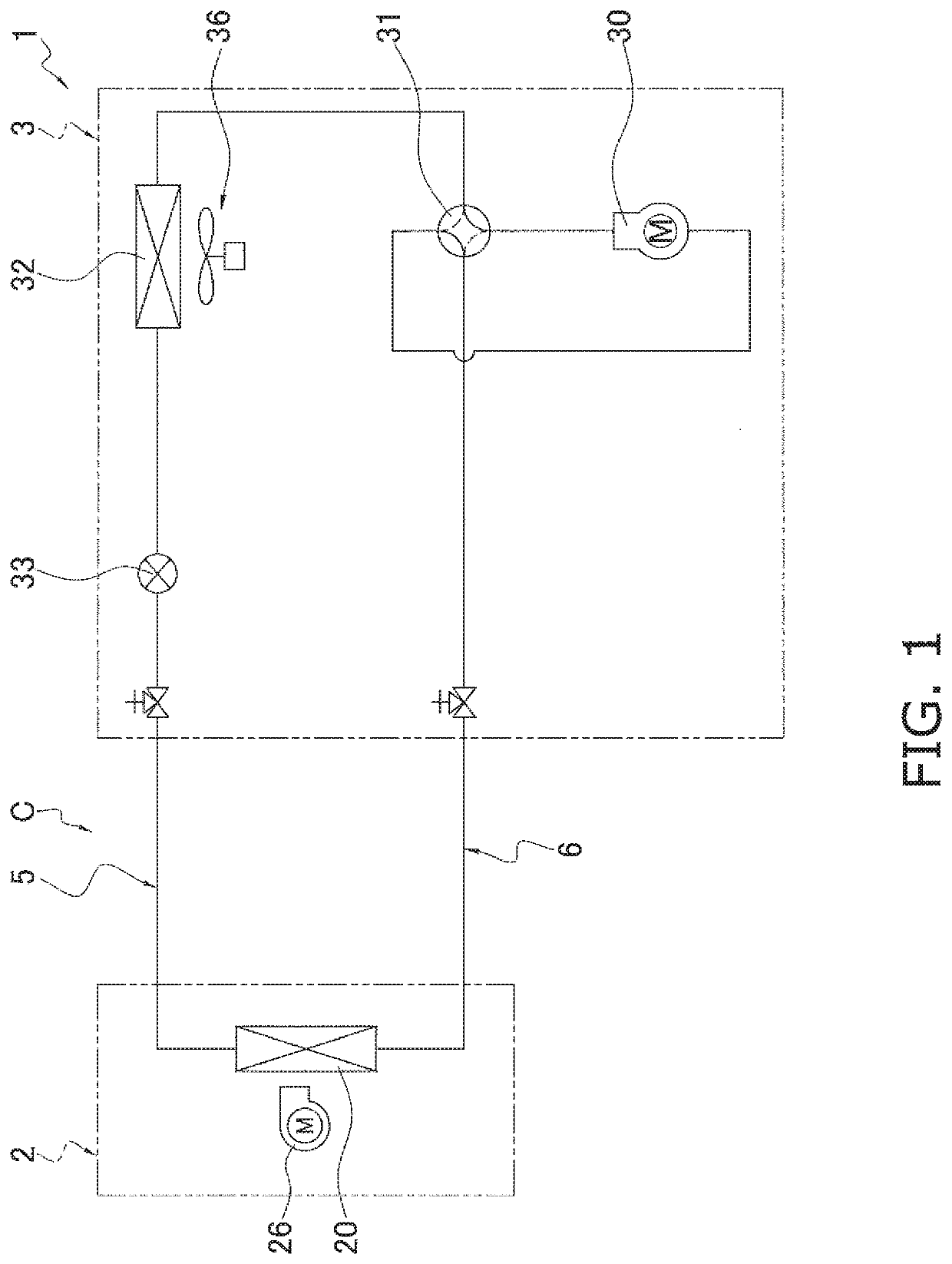
[0034]FIG. 1 is a refrigerant circuit diagram of an air conditioner 1 according to one or more embodiments of the present invention. In FIG. 1, the air conditioner 1 includes an indoor unit 2 and an outdoor unit 3 that is coupled to the indoor unit 2 via pipes 5 and 6. Ordinarily, the indoor unit 2 is set indoors, and the outdoor unit 3 is set outdoors.

[0035]The air conditioner 1 includes a refrigerant circuit C in which a refrigerant circulates. In the refrigerant circuit C, an indoor heat exchanger 20 that belongs to the indoor unit 2, and a compressor 30, a four-way switching valve 31, an outdoor heat exchanger 32, and an expansion valve 33 that belong to the outdoor unit 3 are connected to each other.

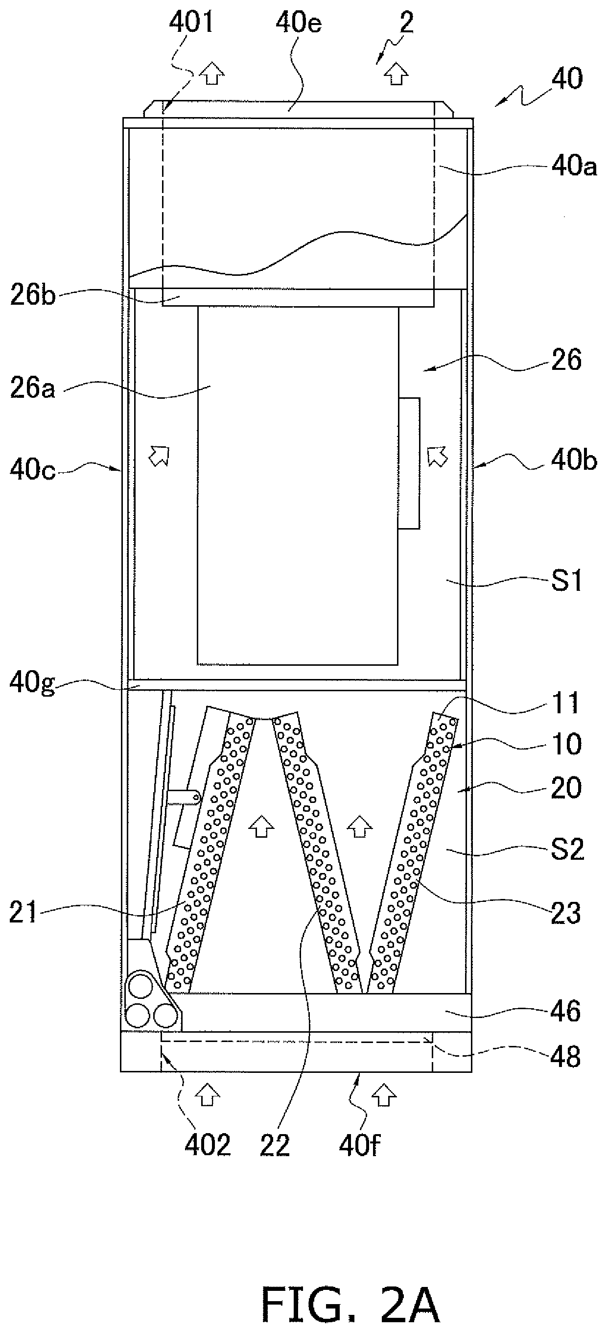
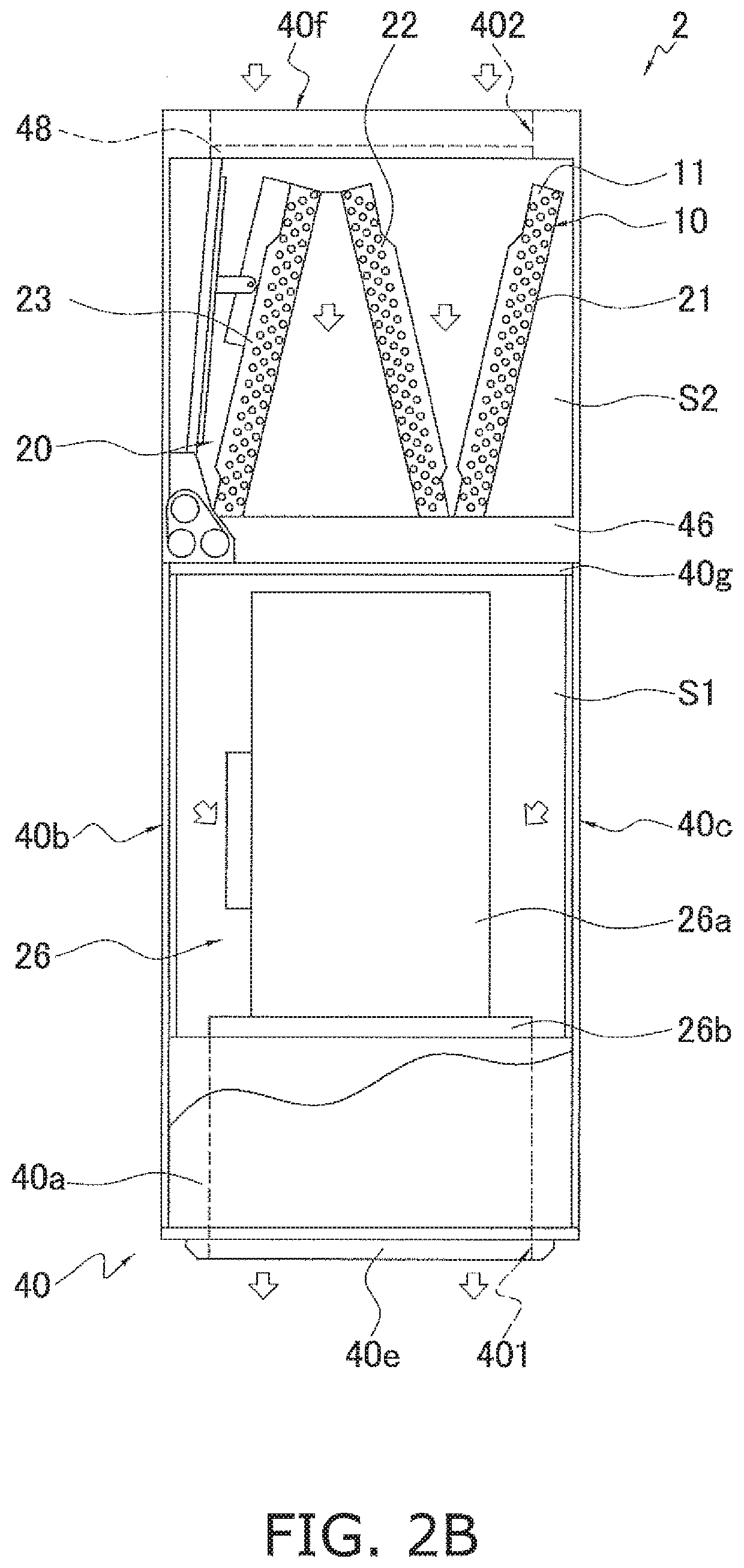
[0036]The indoor unit 2 incl...


PUM


Abstract

A heat exchanger unit includes: a heat exchanging section that includes: a plurality of heat transfer fins; and a plurality of heat transfer tubes that each passes through a corresponding one of the plurality of heat transfer fins, in which, in the heat exchanging section, the plurality of heat transfer tubes that are arranged in L or more levels in a direction that intersects an air flow and in M rows in a direction of the air flow, each of the plurality of heat transfer tubes belongs to one of N paths, an inlet of each of the N paths is disposed at a first end of the heat exchanging section in a level direction, an outlet of each of the N paths is disposed at a second end of the heat exchanging section in the level direction, and M<N.

Description

CROSS-REFERENCE TO RELATED APPLICATIONS[0001]Priority is claimed to Japanese Patent Application No. 2016-256424 filed on Dec. 28, 2016, the entire content of which is incorporated herein by reference.TECHNICAL FIELD[0002]The present invention relates to a heat exchanger unit, particularly, to a heat exchanger unit that may be set such that a facing air flow is reversed, and to an air conditioner using the same.BACKGROUND[0003]In a unitary indoor unit, such as that disclosed in Patent Literature 1 (U.S. Pat. No. 7,003,972), in which a heat exchanger unit and a blower are arranged vertically, the position of the heat exchanger unit and the position of the blower may be reversed due to the demands of the market. Therefore, a top-blow arrangement in which the blower is at an upper side and a bottom-blow arrangement in which the blower is at a lower side are required to provide the same heat exchange performance.[0004]However, when the vertical arrangement of the heat exchanger unit and ...

Claims


Application Information

Patent Timeline
IPC IPC(8): F24F1/0067F28D1/053F28F1/32F28D1/047
CPCF24F1/0067F28D1/05341F28F1/32F25B39/04F25B39/02F28D1/0477F28F2210/02F28D1/0435F28D2001/0266
Inventor KAMADA, TOSHIMITSU
Owner DAIKIN IND LTD
Why Eureka
Try Eureka