
Method for mfg of semiconduceor device

A technology of semiconductors and oxide semiconductors, applied in semiconductor/solid-state device manufacturing, semiconductor devices, electrical components, etc., can solve problems such as reducing contact resistance, reducing dose, and reducing mobility

Inactive Publication Date: 2004-03-24
SK HYNIX INC
View PDF0 Cites 5 Cited by
  • Summary
  • Abstract
  • Description
  • Claims
  • Application Information

AI Technical Summary

Problems solved by technology

These states cause a decrease in mobility on the surface when diffusion occurs in the longitudinal and horizontal directions of the junction, and as a result, the drain saturation current decreases and the dose of dopants implanted by dopant diffusion decreases, thereby reducing the contact resistance

Method used

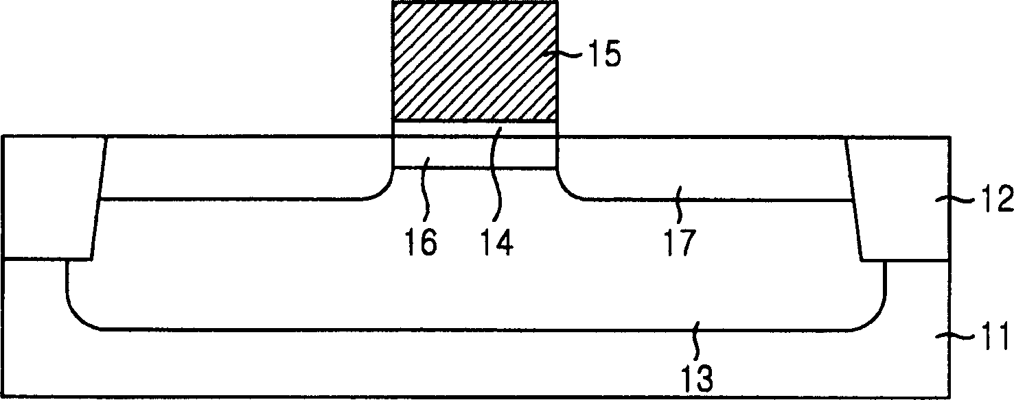
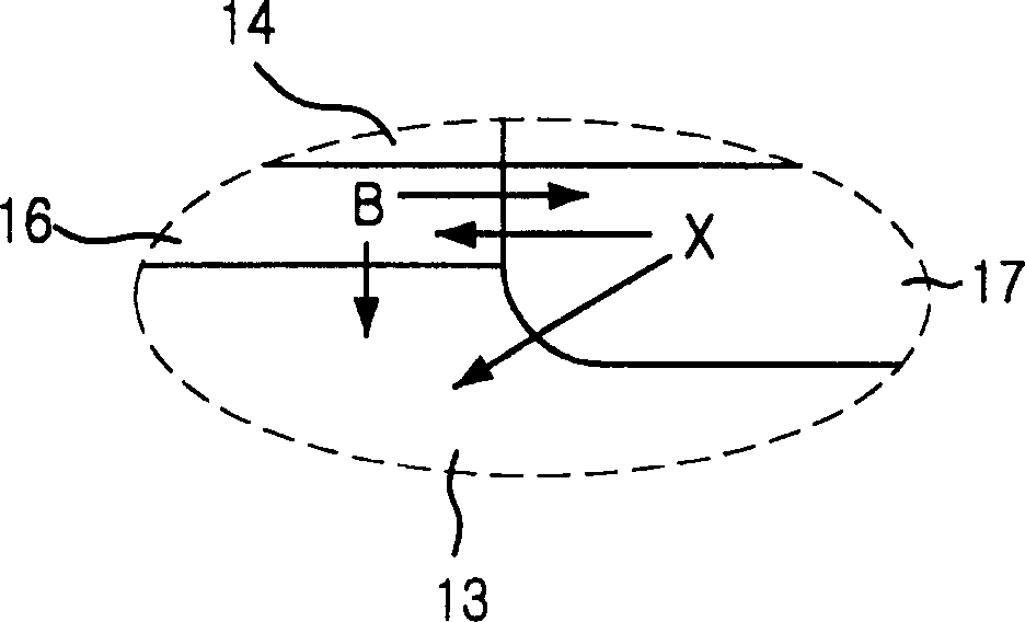

Image

  • Method for mfg of semiconduceor device
  • Method for mfg of semiconduceor device
  • Method for mfg of semiconduceor device

Examples


Embodiment Construction

[0024] Hereinafter, preferred embodiments of the present invention will be described in detail with reference to the accompanying drawings.

[0025] In the preferred embodiments described below, the method for improving short channel characteristics is achieved by avoiding boron isolation from the semiconductor substrate as the channel and bulk region, but also by achieving uniformity of dopant in the channel region degree to implement. This is achieved by inhibiting components, such as intrusive defects, from entering the semiconductor substrate as channel and body regions, i.e. by increasing Electroactivation of boron in the dopant reduces the amount of deactivation.

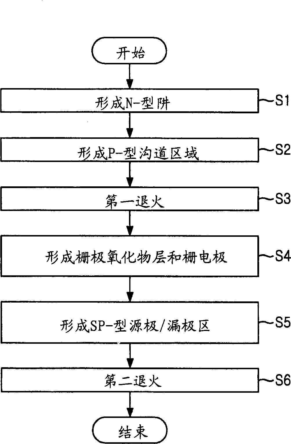
[0026] figure 2 A flow chart showing a PMOS device according to a preferred embodiment of the present invention.

[0027] Such as figure 2 As shown, the method for manufacturing a PMOS device includes a process (S1) for forming an n-type well; a process (S2) for forming a p-type channel region; a process...


PUM


Abstract

A method for forming a p-channel metal-oxide semiconductor(PMOS) device is suitable for reducing the width of change of a threshold voltage by preventing a deterioration of a uniformity of dopants due to out diffusion and segregation of the dopants implanted into channel regions. The method includes the steps of: forming a channel region below a surface of a semiconductor substrate; activating dopants implanted into the channel region through a first annealing process performed twice by rising temperature velocities different to each other; forming a gate oxidation layer and a gate electrode on the semiconductor substrate subsequently; forming a source / drain regions at both sides of the gate electrode in the semiconductor substrate; and activating dopants implanted into the source / drain regions through a second annealing process performed at the same conditions of the first annealing process.

Description

technical field [0001] The present invention relates to a semiconductor memory device, and more particularly to a method for fabricating a semiconductor device with improved channel characteristics. Background technique [0002] As semiconductor devices are integrated, the channel length gradually decreases. Although the size of the device becomes reduced, the concentration of the source and drain is still very high to increase its speed. [0003] As the distance between source and drain becomes shorter, the short channel length makes the threshold voltage (V T ) drops rapidly. The threshold voltage (V T ) will increase the leakage current in the atmosphere, and also cause breakdown of the source and drain, deteriorating the characteristics of the device. In particular, in p-channel metal-oxide-semiconductor (PMOS) devices, the main carriers are holes, and the mobility of carriers in PMOS is the same as that of n-channel metal-oxide-semiconductor (NMOS). The mobility of...

Claims


Application Information

Patent Timeline
IPC IPC(8): H01L21/336H01L21/324H01L29/10
CPCH01L29/1033H01L21/324H01L21/2658H01L29/66575H01L29/78H01L21/18
Inventor 柳昌雨
Owner SK HYNIX INC
Learn More