Spiral sonar

a spiral wave and sonar technology, applied in the field of spiral wave font sonar, can solve the problems of not operating in real time and add to system complexity, and achieve the effects of reducing hardware and data acquisition complexity, reducing cost, and elegant hardware design

Active Publication Date: 2019-11-14
THE UNITED STATES OF AMERICA AS REPRESENTED BY THE SECRETARY OF THE NAVY
View PDF0 Cites 1 Cited by
  • Summary
  • Abstract
  • Description
  • Claims
  • Application Information

AI Technical Summary

Benefits of technology

[0007]Two embodiments of the invention include inventive spiral sonar systems (e.g., spiral transducer array, hydrophone receiver, amplifiers, and / or data acquisition modules). A first spiral sonar system uses a transmit array capable of emitting both a circular (reference) and spiral (probe) acoustic signal. A second spiral sonar system uses a transmit / receive switch to utilize the reference element as a hydrophone, further reducing the number of physical channels.
[0008]An embodiment of the invention can be used wherever more conventional sonars are used. However, because a single channel is used on return in the above-mentioned embodiments of the invention, these embodiments of the invention have decreased complexity; and lower cost; they outperform conventional sonars in sparse environments.
[0010]A salient feature of spiral sonar according to an embodiment of the invention is that the complexity of hardware and data acquisition is much lower than that of conventional imaging sonars, such as multi-beam, side scan, and synthetic aperture sonars. Due to the elegance of the hardware design, it is able to be deployed at a much lower cost than such conventional sonars. For example, an embodiment of the invention uses a small number of channels (e.g., as few as three) to achieve the real-time special resolution of a conventional single-ping active sonar with a large number of channels.

Problems solved by technology

Because each channel requires digitization hardware and software, this adds greatly to system complexity.
Such conventional multi-ping active sonars can have fewer channels than conventional single-ping sonars, but they do not operate in real time, unlike conventional single-ping sonars.
Additionally, such conventional multi-ping active sonars need to retain a large amount of data to reconstruct the final product.

Method used


Image

  • Spiral sonar
  • Spiral sonar
  • Spiral sonar

Examples


Embodiment Construction

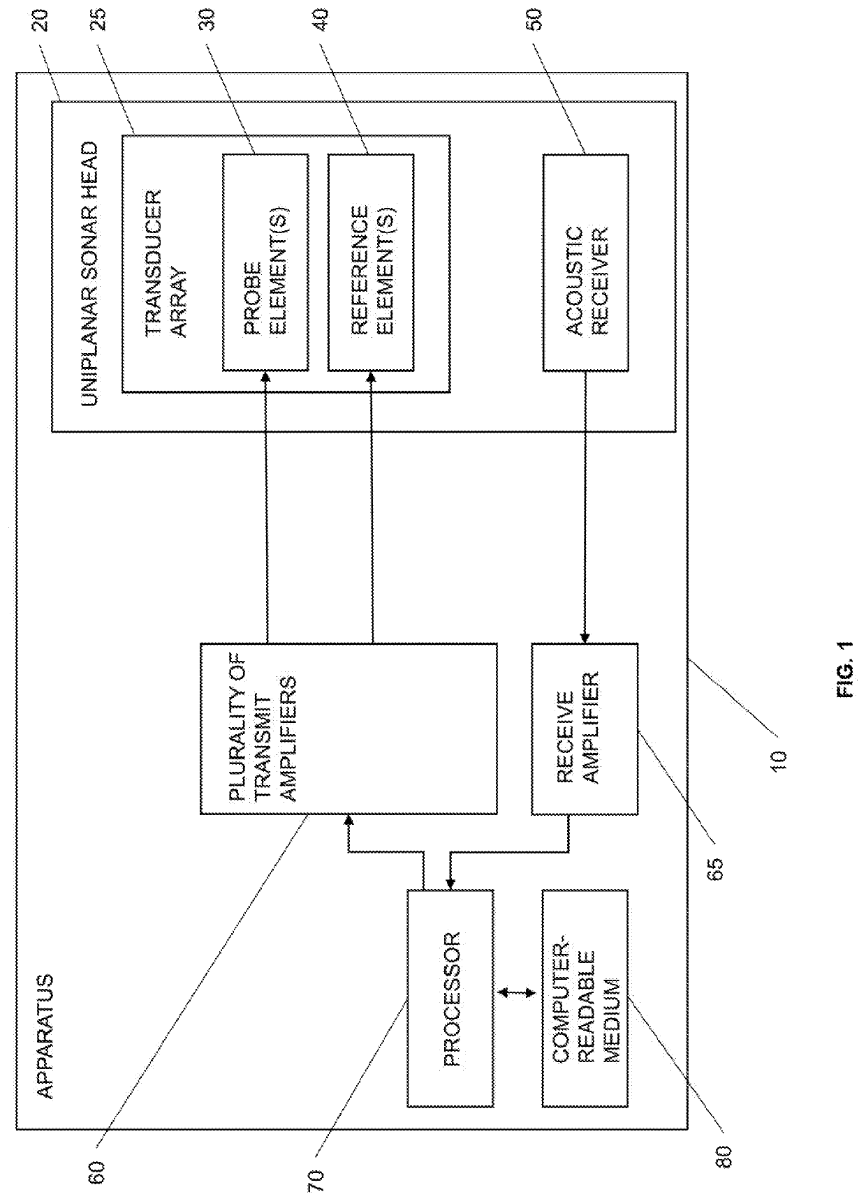
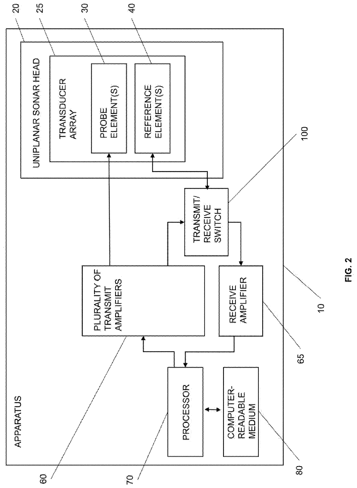
[0014]An embodiment of the invention includes an apparatus 10 for active sonar and is described as follows by way of example in FIGS. 1 and 2. The apparatus 10 includes a standard uniplanar sonar head 20. The uniplanar sonar head 20 includes a transducer array 25 for the transmission of acoustic signals. The transducer array 25 includes at least one standard acoustic probe element 30. Although the at least one probe acoustic probe element optionally includes a plurality of acoustic probe elements, for ease of understanding of FIGS. 1 and 2, only one acoustic probe element is shown. The at least one probe element 30 is configured to output cooperatively a unipolar spiral probe signal that comprises a spiral acoustic wavefront having a phase that varies linearly with angular position in a plane across at least one frequency. The transducer array 25 also includes at least one standard reference element 40. Although the at least one acoustic reference element optionally includes a plura...


PUM


Abstract

An apparatus including a uniplanar sonar head. The uniplanar sonar head includes at least one probe element being configured to output cooperatively a unipolar spiral probe signal. The uniplanar sonar head includes at least one reference element being configured to output a circular reference signal. The uniplanar sonar head includes an acoustic receiver comprising an input channel being configured to receive a reflected unipolar spiral probe signal and a reflected circular reference signal. The apparatus includes a plurality of amplifiers communicating with the at least one probe element, the at least one reference element, and the acoustic receiver. The apparatus includes a processor cooperating with the plurality of amplifiers. The apparatus includes a computer-readable medium storing instructions including a target-detection method, which includes determining an angular position of the target based on the plurality of acoustic echoes received via the input channel.

Description

CROSS-REFERENCE TO RELATED APPLICATIONS[0001]The present application claims priority to U.S. Provisional Patent Application Ser. No. 62 / 668,956, which was filed on 9 May 2018 and is incorporated herein by reference.BACKGROUND OF THE INVENTIONField of the Invention[0002]This invention relates in general to an apparatus for active sonar, and in particular to an apparatus for spiral wave font sonar.Description of the Related Art[0003]Traditional single-ping active sonar systems rely on spatial aperture and time-of-flight to resolve the location of scatterers in its field of view. To achieve greater resolution, the aperture must be populated with a large number of hydrophones (or, less commonly acoustic projectors). Scatterer position is determined by looking at the phase difference (or equivalently, time-of-flight differences) between channels. Thus, conventional single-ping active sonar have a large number of input (or output) channels to achieve a resolution needed for the complex ta...

Claims


Application Information

Patent Timeline
Patent Type & Authority Applications(United States)
IPC IPC(8): G01S15/42G01S15/58G01S7/527G01S7/524G01S7/539
CPCG01S7/527G01S7/524G01S15/42G01S15/58G01S7/539G01S15/104
Inventor DZIKOWICZ, BENJAMIN R.
Owner THE UNITED STATES OF AMERICA AS REPRESENTED BY THE SECRETARY OF THE NAVY
Why Eureka
Try Eureka