
Method for Casting a Construction Element and a Mould for Use in the Method

Inactive Publication Date: 2019-11-21
IMMENSA TECH LABS FZ LLC
View PDF0 Cites 1 Cited by
  • Summary
  • Abstract
  • Description
  • Claims
  • Application Information

AI Technical Summary

Benefits of technology

The patent text describes an additive manufacturing technique called 3D printing, which uses an adhesive dispensing system to strengthen and rigidify articles being printed. This process can be used to make molds and conduits from plastic materials. The use of adhesive helps improve the strength and performance of plastic materials, making them more suitable for various applications.

Problems solved by technology

One major drawback with conventional methods of producing moulds, is that, due to the complexity and intricate design, it is not always possible to produce moulds for casting construction elements having intricate and or complex shapes.
Another major drawback with conventional methods of producing moulds, is that, due to the complexity and intricate design, it is not always cost effective to produce moulds for casting construction elements having intricate and or complex shapes.
It will be appreciated that, using known methods for making moulds, as the intricacy and complexity increases, it becomes more and more labour intensive to produce moulds having increased intricacy and complexity.
It is therefore very time consuming and therefore expensive to use conventional methods of manufacturing moulds for casting construction elements having intricate and or complex shapes.
Reinforcing of moulds produced using conventional methods is also time consuming and therefore disadvantageous.

Method used


Image

  • Method for Casting a Construction Element and a Mould for Use in the Method
  • Method for Casting a Construction Element and a Mould for Use in the Method
  • Method for Casting a Construction Element and a Mould for Use in the Method

Examples


Embodiment Construction

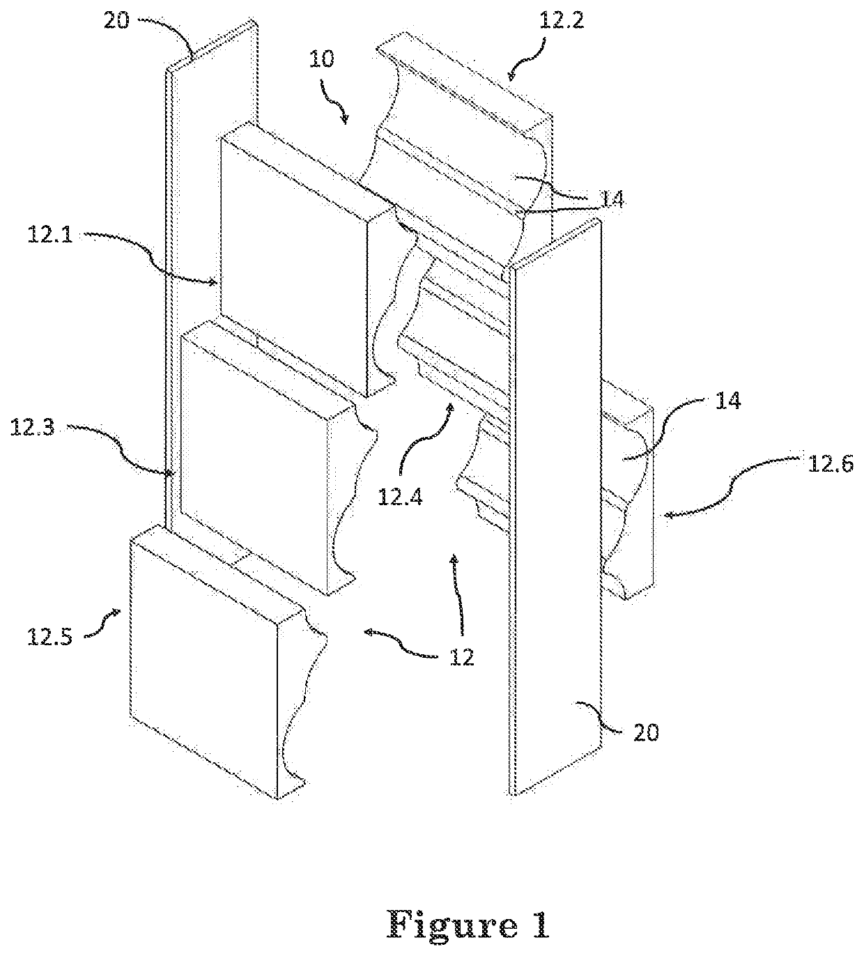
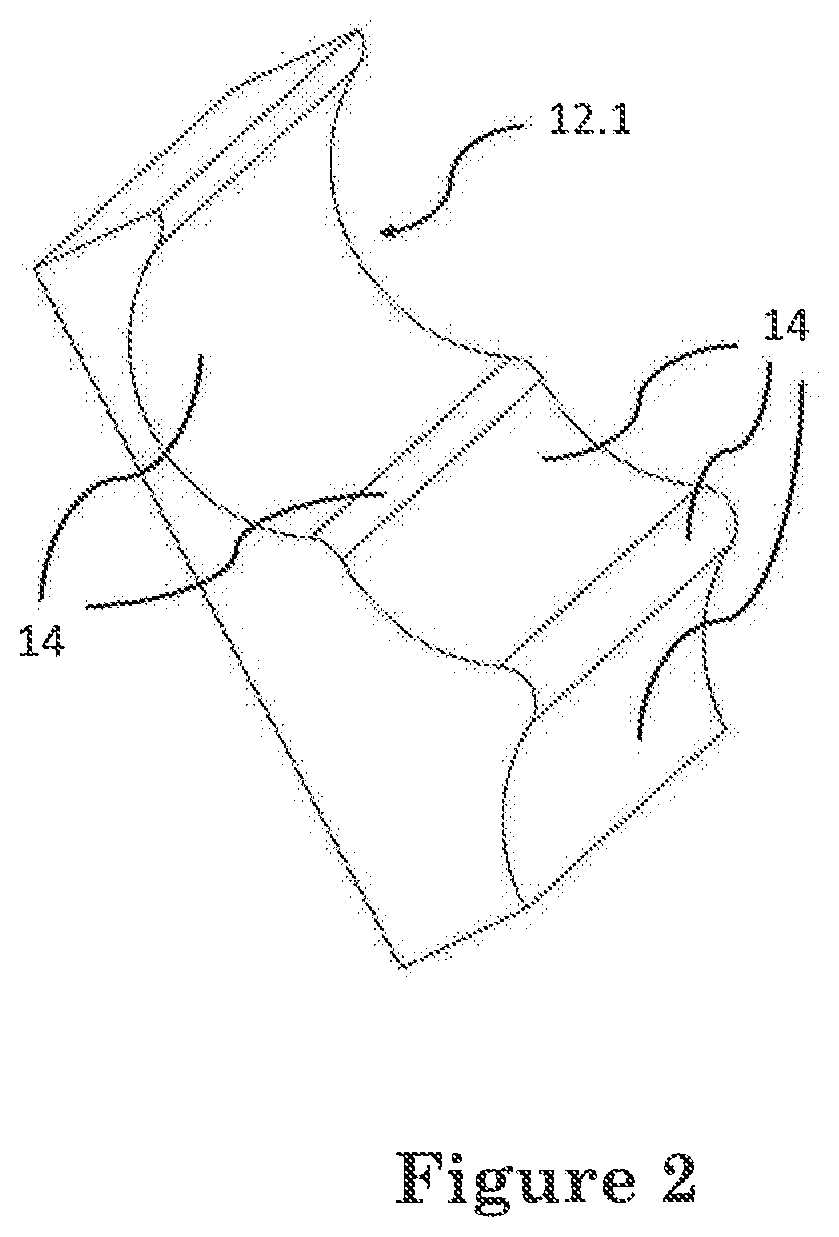
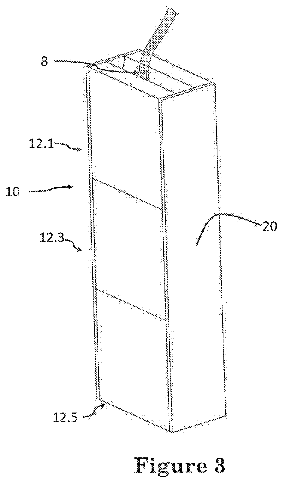
[0050]With reference to FIGS. 1 to 5 of the drawings, a mould, in accordance with the invention, for casting a construction element 6 from settable material 8, is indicated generally by the reference numeral 10. The settable material 8 can be any suitable type of material for building, such as, for example, concrete.

[0051]The mould 10 includes a number of mould bodies 12 in the form of complementary mould-halves 12.1, 12.2, 12.3, 12.4, 12.5, and 12.6, the mould 10 further includes a polymeric material (not shown) applied to each mould-halves for reinforcing each mould-half.

[0052]Each mould-half is formed by an additive manufacturing technique and comprises a negative of a construction element to be cast. The additive manufacturing technique is, more particularly, in the form of a layer additive manufacturing technique, such as, for example, a three-dimensional (3D) printing technique. The 3D printing technique includes an adhesive dispensing system for dispensing an adhesive onto th...


PUM

PropertyMeasurementUnit
Strengthaaaaaaaaaa

Abstract

A method for casting a construction element includes: using a CAD technique designing mould bodies 12 comprising mould-halves 12.1, 12.2, 12.3, 12.4, 12.5, 12.6, 12.7, 12.8; printing the mould-halves on a 3D printer which includes an adhesive dispensing system; providing a locating formation 16 on mould-half 12.7; reinforcing the mould-halves with two polyurethane or polyurea coatings; applying form wax to the mould-halves; printing a conduit 18 on a 3D printer; locating the mould-halves at a construction site and securing the mould halves to one another; locating the conduit 18 relative to the mould-halves by means of the locating formation 16; pouring concrete into the assembled mould so as to embed the conduit 18 within the concrete; and allowing the concrete to cure; removing the mould-halves and repeating a desired number of times.

Description

CROSS-REFERENCE TO RELATED APPLICATIONS[0001]This application claims the benefit of priority under 35 U.S.C. § 119 to United Arab Emirates patent application UAE P6000683 / 2018, tiled on May 17, 2018, the disclosure of which is incorporated herein by reference in its entirety.BACKGROUND OF THE INVENTION1. Field of the Invention[0002]This invention relates to a method for casting a construction element and to a mould for use in the method.2. Discussion of Related Art[0003]The use of moulds for casting construction elements are generally well known. Known moulds are typically constructed from sheet material, such as, for example wooden boards or steel sheeting.[0004]One major drawback with conventional methods of producing moulds, is that, due to the complexity and intricate design, it is not always possible to produce moulds for casting construction elements having intricate and or complex shapes. Another major drawback with conventional methods of producing moulds, is that, due to th...

Claims


Application Information

Patent Timeline
IPC IPC(8): B28B1/14B29C64/106B28B7/36B28B7/34
CPCB33Y80/00B33Y10/00B29L2031/757B28B7/346B28B7/362B29C64/106B28B1/14B28B7/364B28B23/0025B29C64/112E04B2/84E04G9/05E04G9/10H02G3/22
Inventor DUGBENOO, EDEM KWABLAELDIK, ELIAS GEORGES
Owner IMMENSA TECH LABS FZ LLC
Learn More