
Paperboard cartons with laminated reinforcing ribbons and method of making same

Inactive Publication Date: 2012-11-27
GRAPHIC PACKAGING INT
View PDF121 Cites 31 Cited by
  • Summary
  • Abstract
  • Description
  • Claims
  • Application Information

AI Technical Summary

Benefits of technology

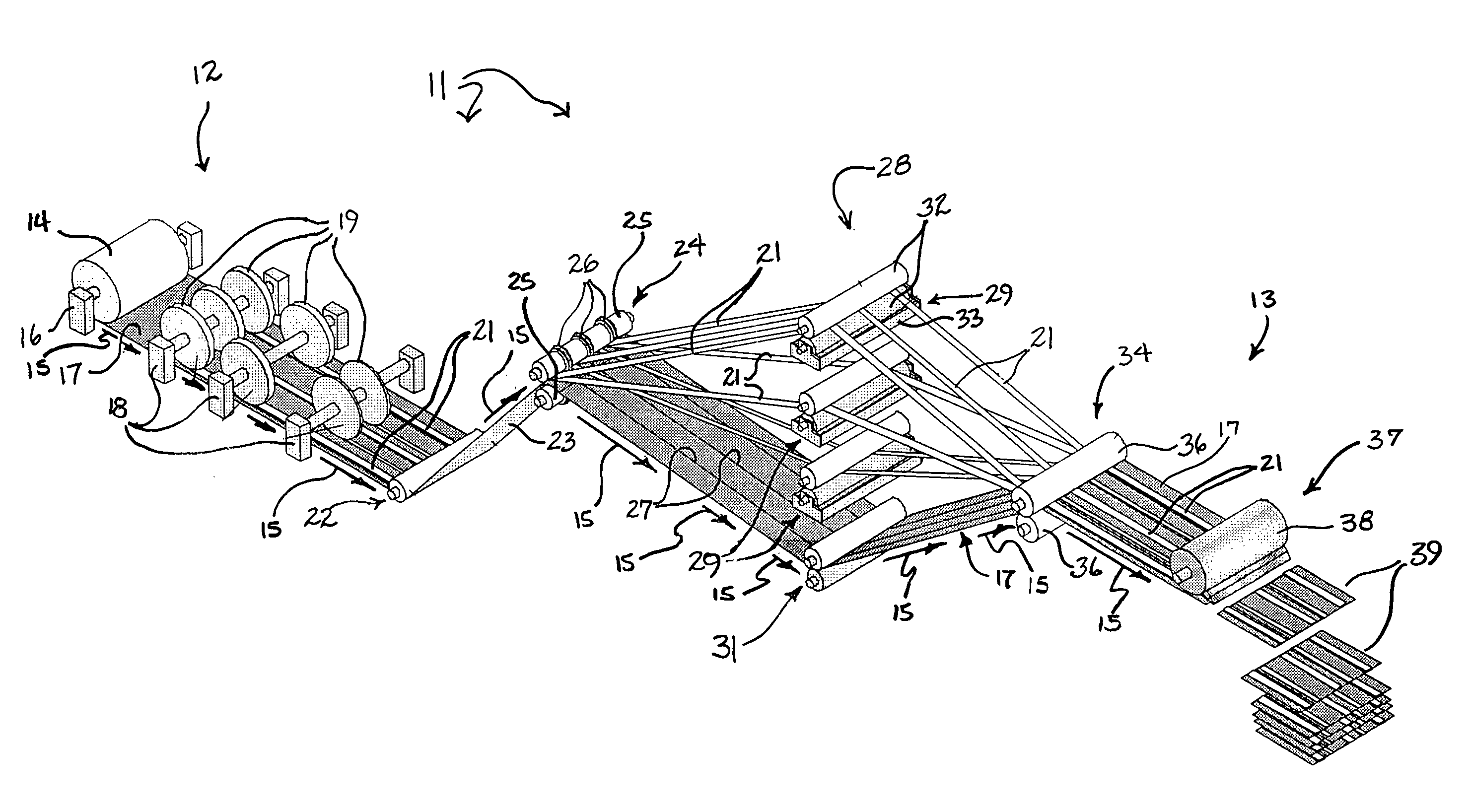
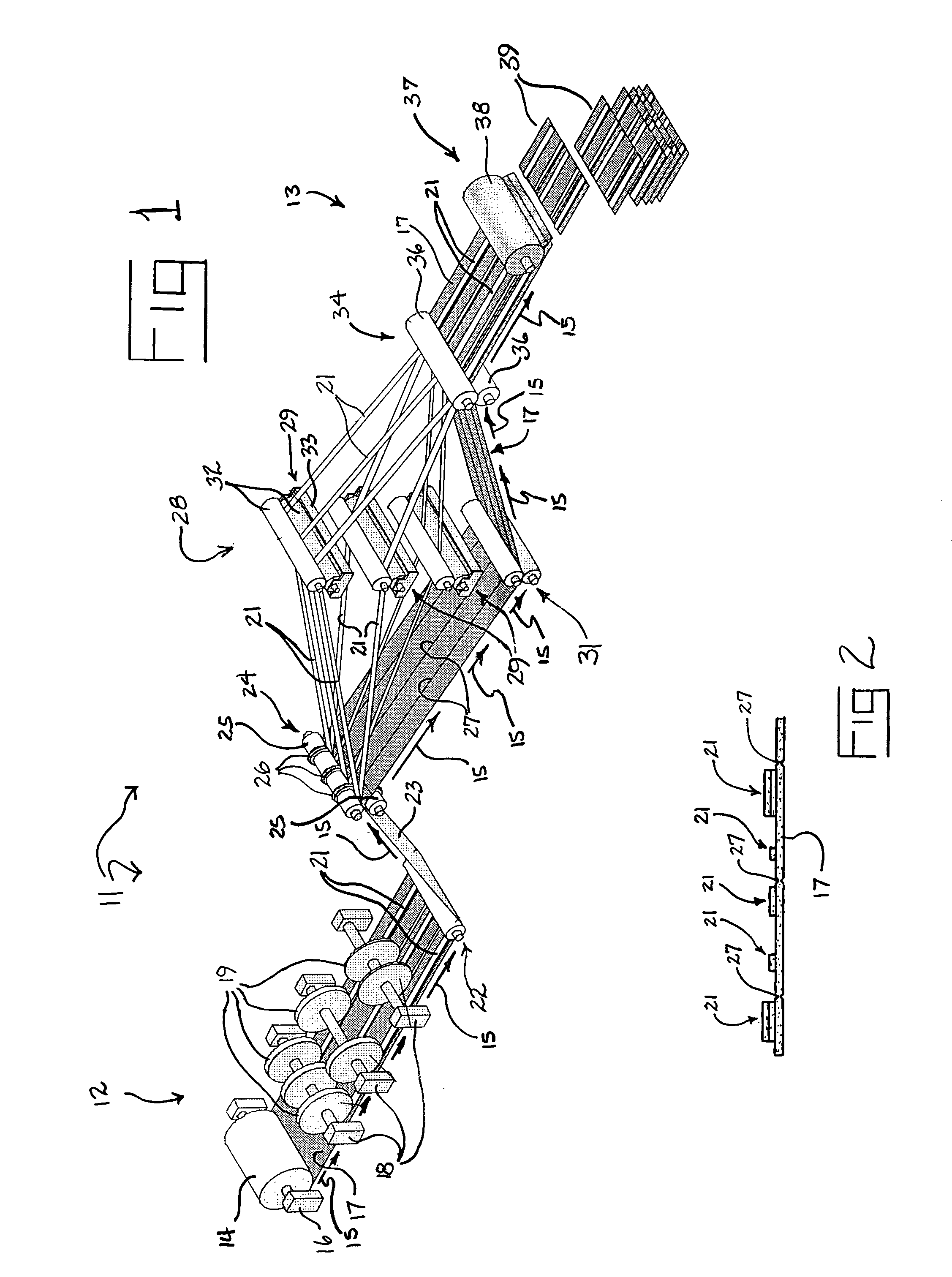
[0015]As the web of paperboard is advanced along the path, one or more ribbons of reinforcing material, each having a width less than the width of the paperboard web, is progressively applied to the web. Each ribbon preferably is applied with adhesive to the side of the web that will become the inside of the finished cartons and is positioned at a predetermined location across the width of the web. The location of each ribbon is selected to provide multiple layers or laminations of material in specific regions of finished cartons where enhanced strength and / or rigidity will be required such as, for example, in the side walls of the carton. Preferably, the ribbons of reinforcing material also are formed of paperboard and most preferably are pre-cut or slit to desired widths from paperboard trim or cull that otherwise may have reduced value. The ribbons are drawn from rolls that are pre-positioned to locate the ribbons properly on the web, advanced along and adjacent to the path of the web, supplied with adhesive on one side, and progressively brought into engagement with and compressed against the advancing paperboard web to adhere the ribbons to the web. In one embodiment, one or more of the ribbons may be pre-printed or on both sides with application specific indicia that ultimately will be exposed on the inside of finished cartons.
[0016]After the reinforcing ribbons are laminated to the advancing web, the web may be cut into sheets of a predetermined size. The sheets subsequently may be die-cut and scored with fold lines as required to form carton blanks defining the various panels and tabs that ultimately will become the walls of finished cartons. The carton blanks may be palletized and shipped to packagers, where the blanks are converted into cartons and packed with articles such as, for example, beverage containers or food items. When converted to cartons, the JD previously positioned and applied paperboard reinforcing ribbons form multiple layers or laminations of paperboard in selected portions of the cartons such as, for example, in their sides, where enhanced structural integrity is required. By appropriately selecting, sizing, and positioning the reinforcing ribbons, paperboard cartons having strength and rigidity comparable or superior to that provided by cartons made of micro-flute are obtained. Further, through judicious use of trim and cull in making the reinforcing ribbons, paperboard cartons made by the method of the present invention can be economically viable alternatives to cartons made of micro-flute.

Problems solved by technology

In general, the creation of trim in the process of making paperboard web has long been a problem for paperboard manufacturers.
Occasionally, errors by paperboard manufacturers result in rolls of paperboard web that may be substandard for a variety of reasons and thus not usable in the fabrication of paperboard cartons.
In other cases, paperboard web manufactured for a particular customer may not meet specifications and thus cannot readily be used.
This is because the individual drink containers lack the rigidity of bottles or cans and cannot themselves bear the entire weight of a stack of cartoned fruit drinks.
In applications such as these, traditional paperboard cartons have sometimes proven inadequate to provide the required strength and rigidity.
Micro-flute does tend to provide the strength and rigidity required in many packaging applications; however, it also has significant inherent problems and shortcomings including its generally higher price compared to paperboard.
In addition, carton blanks made of micro-flute can be more expensive in some weights to ship than paperboard blanks because their greater thickness limits the number of blanks that can be stacked on standard sized pallet.
Further, in some cases, specialized conversion machinery is required to convert the blanks to cartons, increasing the cost of the packaging process.
Finally, the printing of high quality graphics on micro-flute has sometimes proven to be difficult.
Thus, micro-flute has not provided a completely satisfactory solution as a carton making material in packaging applications where enhanced carton strength and rigidity is required.
However, while this approach increases the strength and rigidity of resulting cartons, it essentially results in a doubling of the paperboard required per carton and a consequent increase in material and shipping costs.
Further, the formation of fold lines in and the folding of multiple ply paperboard cartons is problematic due to the added thickness of paperboard that must be folded.
For these and other reasons, such multi-layer laminated paperboard has not proven to be an acceptable alternative to micro-flute.
However, installing inserts requires expensive specialized machinery, increases material and packaging costs, and can significantly slow the packaging process.
A problem with cartons in general, including micro-flute and paperboard cartons, is that they tend to tear and fail in areas of particularly high stress such as in certain corners of the cartons where folded panels meet.
Such tears, once started, often can do spread, resulting in the separation of carton panels and ultimately in carton blow-out.
Such attempts have not been completely successful.
In the past, such interior printing has required that relatively expensive and time-consuming two-sided printing techniques be used to print both sides of a web from which the carton blanks are cut.
Further, since interior surfaces of cartons generally are not coated for printing, the quality and character of printing available for interior carton surfaces has been limited.

Method used


Image

  • Paperboard cartons with laminated reinforcing ribbons and method of making same
  • Paperboard cartons with laminated reinforcing ribbons and method of making same
  • Paperboard cartons with laminated reinforcing ribbons and method of making same

Examples


Embodiment Construction

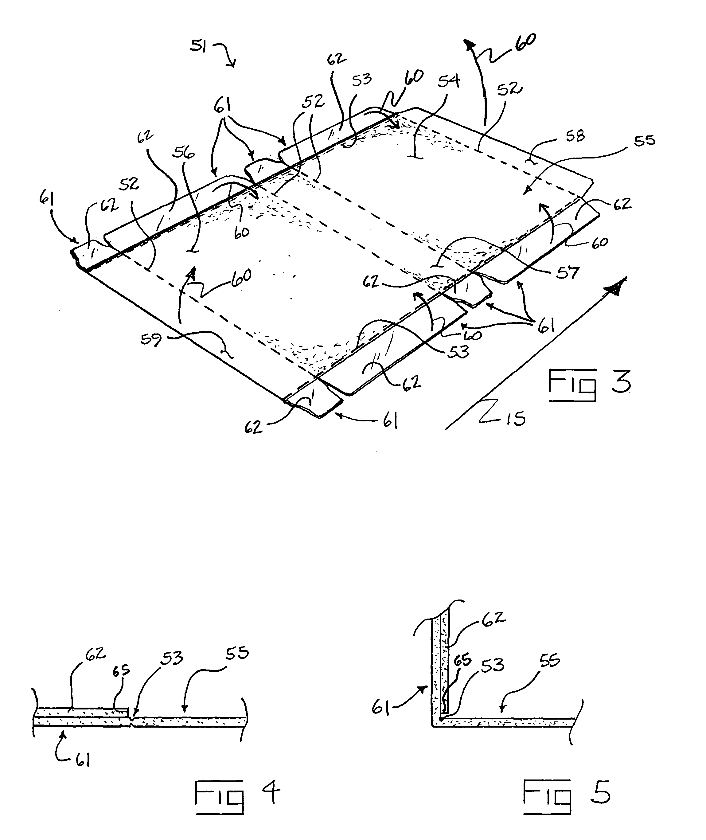
[0027]As mentioned above, carton blanks may be provided in the form of pre-glued knocked down sleeves or completely flat sheets depending upon the type of packaging operation in which they are to be used. The carton blank shown in FIG. 3 is of the former type and typically is partially folded and glued at the carton manufacturing location and shipped to a packager in the form of a knocked down sleeve. This sleeve, then, is erected by the packaging machinery into an open-ended carton sleeve into which product is inserted before the carton sleeve is sealed shut. This type of carton typically is used in most beer and soft drink bottling plants. The carton shown in FIG. 8, on the other hand, typically is formed from a carton blank that is shipped completely flat, folded around product in the packaging machine, and glued shut. This latter type of carton blank is different than the former in that the gluing of the carton to form a sleeve is done at the product production and / or packaging ...


PUM


Abstract

A method of making reinforced paperboard cartons comprises the steps of advancing a web of paperboard along a path and progressively laminating at least one ribbon of reinforcing material to the advancing web of paperboard. The ribbon of reinforcing material, which also may be paperboard, has a width less than the width of the web of paperboard and is applied with adhesive at a selected location across the width of the web. The web and its laminated ribbon are cut into sheets of a predetermined size and the sheets are die-cut and scored with fold lines to form carton blanks. The carton blanks are subsequently formed into cartons for receiving articles, the laminated reinforcing material providing reinforcement in selected portions of the cartons. Multiple ribbons and multiple layers of ribbons may be laminated to the web in respective selected locations to provide reinforcement in more than one portion of the cartons. Reinforced cartons and carton blanks made by the method also are provided.

Description

BACKGROUND OF THE INVENTION[0001]1. Field of the Invention[0002]This invention relates generally to article packaging and more specifically to the fabrication of paperboard cartons into which a plurality of articles can be packaged for transport and sale.[0003]2. Description of the Related Art[0004]Paperboard cartons of various design and construction have long been used by the packaging industry to package a wide variety of articles such as canned and bottled drinks, food items, detergents, and more. In general, paperboard cartons are erected or converted from paperboard blanks that are die-cut or rotary-cut from long webs of paperboard as the paperboard is drawn progressively from large rolls. Fold lines are scored in the blanks to define the various panels of the cartons and to aid in the conversion of the blanks into their final carton shapes. In some cases, such as in beer and soft drink packaging, the blanks are pre-glued and provided to packager in the form of substantially f...

Claims


Application Information

Patent Timeline
IPC IPC(8): B31B1/72B65D5/43B31B1/90B31B7/00B31B50/16B31B50/25B31B50/62B31B50/72B31B50/88B65D5/44B65D5/49
CPCB31B1/25B31B1/90B31B7/00B65D5/445B65D5/48024B31B2201/9038B31B2201/9052B31B2217/0084B31F1/10B31B2201/257B31B2120/40B31B2105/00B31B50/256B31B50/8126B31B50/8129B31B2105/001
Inventor ZOECKLER, MICHAEL D.
Owner GRAPHIC PACKAGING INT
Learn More