Process for purification of a synthesis gas containing hydrogen and impurities

Active Publication Date: 2016-05-26
CASALE SA
View PDF7 Cites 0 Cited by
  • Summary
  • Abstract
  • Description
  • Claims
  • Application Information

AI Technical Summary

Benefits of technology

[0019]Methanation consumes some hydrogen, for example around 3% of the hydrogen contained in the syngas, thus it appears to reduce the value of the syngas, for example the amount of ammonia that can be synthesized at fixed syngas capacity. For this reason, in a conventional process with LNW it was preferred to remove completely the carbon dioxide by adsorption upstream the LNW. The applicant has found that, despite the above drawback of some hydrogen consumed, it is surprisingly advantageous to combine methanation and cryogenic purification such as LNW. More in detail, the applicant has found that the above combination is advantageous to the overall process because of the following benefits.
[0020]A first positive effect, compared to the known art, is that adsorption is used to capture water, since residual CO2 is converted during the methanation step. After methanation, a substantial amount of water can be easily removed by air-cooled or water-cooled condensation, so that the actual amount of water to be adsorbed is reduced. As a consequence, much smaller volumes of molecular sieves and a less amount of gas for regeneration are required, compared to prior-art solution where residual carbon dioxide and water are both removed with molecular sieves. The size and cost of molecular sieves drying unit are drastically reduced thanks to the invention.
[0021]Most of the CO2 is normally removed prior to the steps of methanation and cryogenic purification, in a suitable CDR (carbon dioxide removal) unit. Thanks to the invention, there is no need to push the CO2 removal to very low ppm of residual, which is energy intensive and difficult to achieve with o

Problems solved by technology

It cannot be used as regeneration medium for the molecular sieves, since it contains some CO which would decompose at the high temperature of regeneration.
A drawback of a methanator is that it consumes some of the available hydrogen.
As stated above, the preliminary removal of CO2 requires a regeneration gas, normally nitrogen or a portion of synthesis gas, which

Method used


Image

  • Process for purification of a synthesis gas containing hydrogen and impurities
  • Process for purification of a synthesis gas containing hydrogen and impurities

Examples


Example

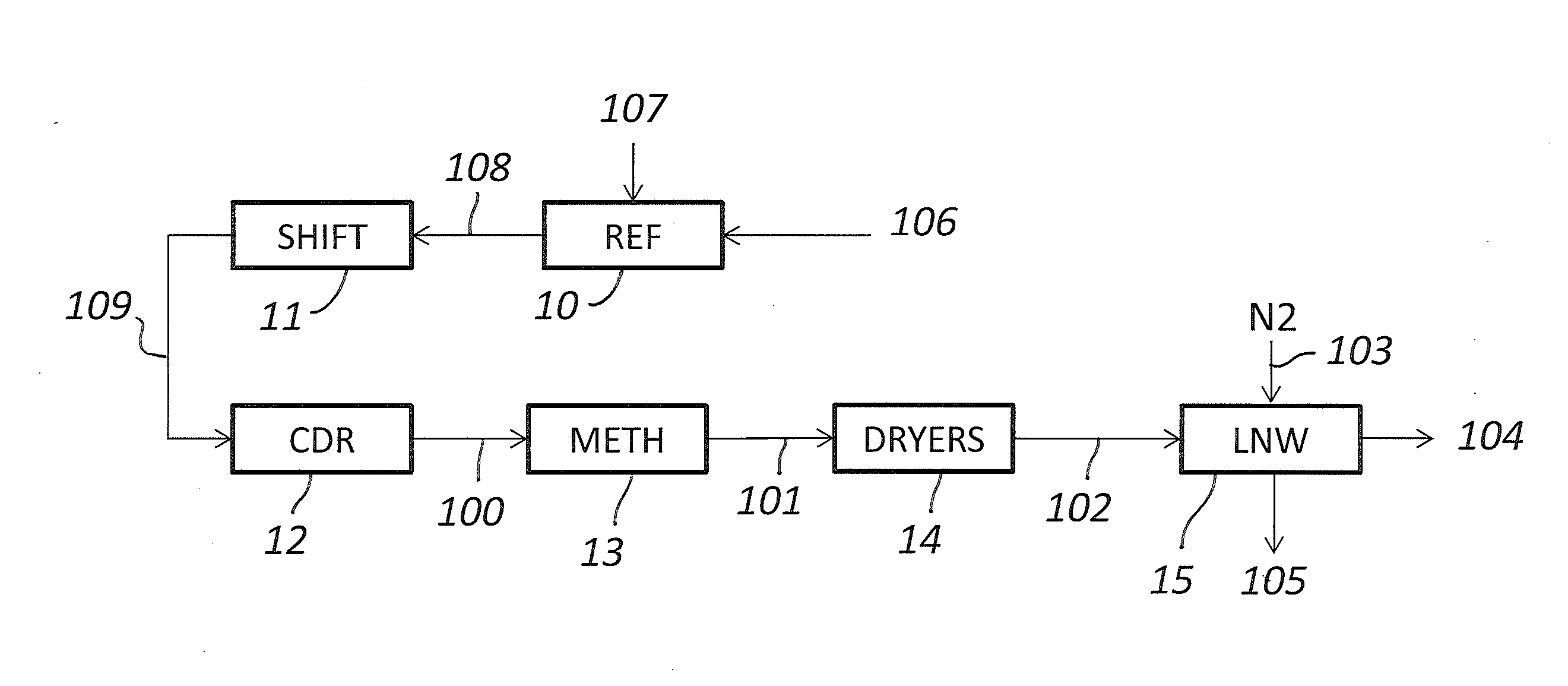
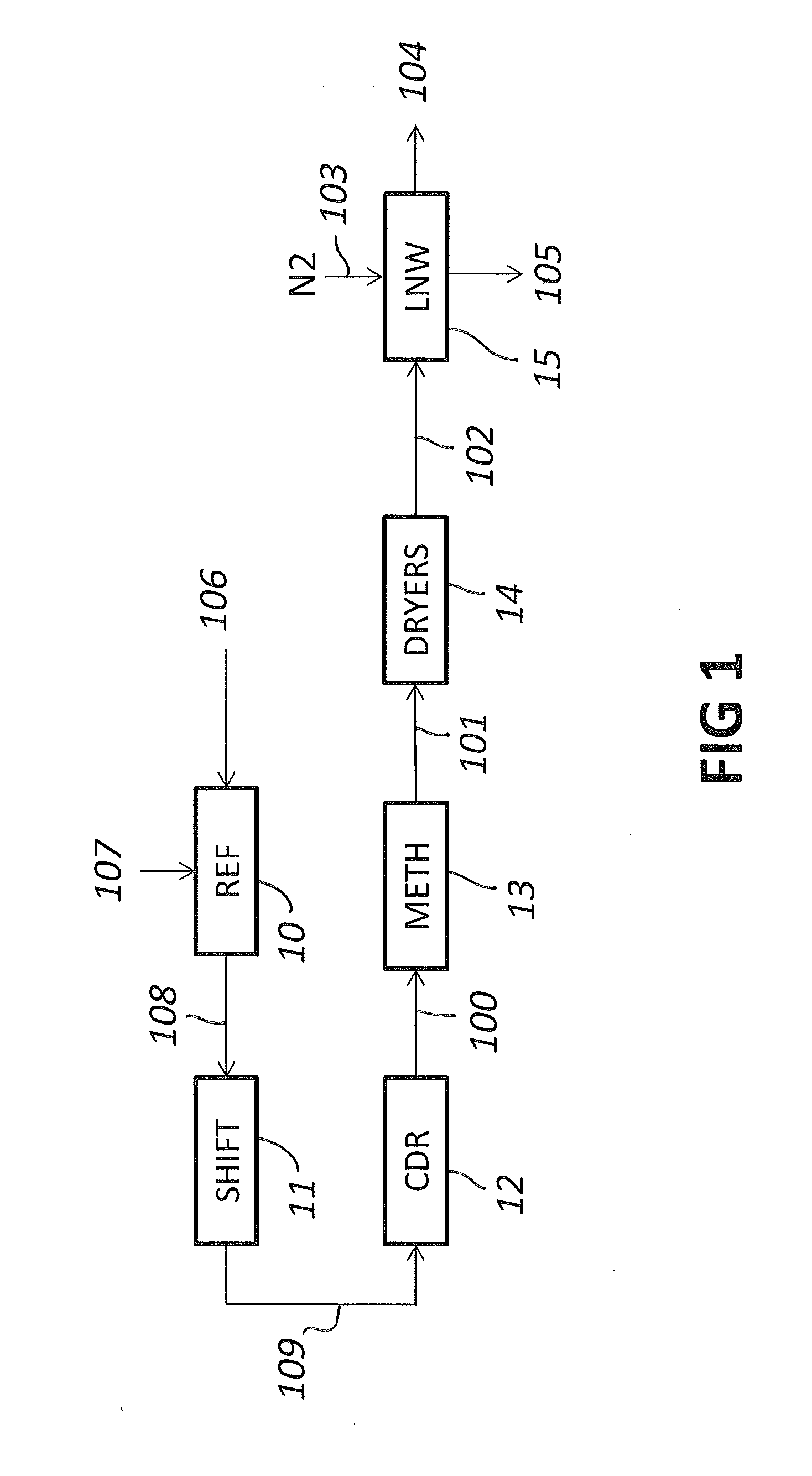
[0030]Referring to FIG. 1, a current of hydrogen syngas 100 is composed mostly of hydrogen (H2), and contains minor amounts of CO, CH4, CO2, N2, Argon and water. For example H2 is more than 90%, preferably more than 95%, CO and CH4 are around 1-2%, and the other components are preferably less than 1%.

[0031]Said current 100 comes from previous treatments of shift and carbon dioxide removal, as will be explained below. Hence the CO and CO2 contained in the current 100 are residual amounts after the above treatment steps.

[0032]Said current 100, according to the shown embodiment, is fed to a methanator 13 where CO and CO2 are converted to methane and water. The syngas 101 leaving the methanator 13 contains practically no CO and CO2, and a certain amount of methane, for example around 3% of methane.

[0033]Said gas 101 is fed to a dehydration unit 14, to remove residual water. The dehydrated gas 102 leaving said unit 14 is sent to a cryogenic purification section, which in the example is e...


PUM


Abstract

A process for purification of a current of hydrogen synthesis gas (100), particularly in the front-end of an ammonia plant, wherein said gas contains hydrogen and minor amounts of carbon monoxide, carbon dioxide, water and impurities, said process including steps of methanation (13) of said current (100), converting residual amounts of carbon monoxide and carbon dioxide to methane and water, dehydration (14) of the gas to remove water, and then a cryogenic purification (15) such as liquid nitrogen wash, to remove methane and Argon; a corresponding plant and method for revamping an ammonia plant are also disclosed.

Description

FIELD OF THE INVENTION[0001]The invention relates to a process for the purification of a hydrogen synthesis gas, particularly in a front-end of an ammonia plant.BACKGROUND ART[0002]The term of hydrogen synthesis gas in this description denotes a synthesis gas mainly composed of hydrogen, and comprising minor amounts of impurities including, for example, carbon monoxide, carbon dioxide, water, methane, argon. The term of syngas will also be used as a short form for synthesis gas.[0003]A hydrogen synthesis gas can be produced for example in the front-end of a plant for the synthesis of ammonia, by reforming a hydrocarbon with a current of oxygen. Upon addition of a proper amount of nitrogen, a make-up gas suitable for the synthesis of ammonia is obtained.[0004]The production of a hydrogen synthesis gas involves basically the following steps: reforming of a hydrocarbon source, such as natural gas, with oxygen; shift conversion, removal of CO2. These steps remove most of the carbon mono...

Claims


Application Information

Patent Timeline
IPC IPC(8): F25J3/08C01B3/02F25J3/02C01B3/58
CPCF25J3/08C01B3/586C01B3/025F25J3/0223C01B2203/0445F25J2220/40C01B2203/047C01B2203/0475C01B2203/068C01B2203/1235C01B2203/046C01B3/506C01B2203/025C01B2203/0283C01B2203/043C01B2203/0495C01B2203/147C01B3/02C01B3/58
Inventor FILIPPI, ERMANNOOSTUNI, RAFFAELECHIESA, DAMIANO
Owner CASALE SA
Why Eureka
Try Eureka