Equipment, display-object component, and display-object fixing method

Active Publication Date: 2019-11-21
ALPINE ELECTRONICS INC
View PDF4 Cites 0 Cited by
  • Summary
  • Abstract
  • Description
  • Claims
  • Application Information

AI Technical Summary

Benefits of technology

The patent text describes a method for easily and inexpensively fixing a display object to equipment using adhesion. This can prevent the user from forgetting to fix the display object and ruining the appearance of the equipment. The text also mentions the use of a tongue-shaped portion to indicate temporary fixation, and the integrated shipment of the equipment body and display-object component to prevent the user from overlooking the display-object component. The technical effects of this patent include improved advertising opportunities for the brand and improved appearance of the equipment.

Problems solved by technology

However, fixation of a display object to equipment usable in a vertical orientation / horizontal orientation, with adhesion, prior to shipment of the equipment, causes a possibility that the display object cannot be made correct in position depending on a mode of use of the vertical orientation / horizontal orientation of the equipment.
However, this manner may cause the user to forget to fix the display object to the equipment and may cause the user to use the equipment without the display object, resulting in a possibility that a problem occurs.
That is, for example, in a case where a display object includes a logo plate displaying a logo of the brand of equipment, a user is a distributor for the equipment, and the distributor exhibits the equipment to which the logo plate is not fixed, loss of the advertising opportunity of the brand or spoiling of the appearance of the equipment may reduce the appeal of the equipment.

Method used


Image

  • Equipment, display-object component, and display-object fixing method
  • Equipment, display-object component, and display-object fixing method
  • Equipment, display-object component, and display-object fixing method

Examples


Embodiment Construction

[0030]An embodiment of the present disclosure will be described below.

[0031]FIGS. 1A to 1D illustrate the relationship between a logo plate and an equipment body according to the present embodiment.

[0032]As illustrated in FIG. 1A, the logo plate 1 has a top face on which the logo of a brand is displayed, the logo determining the top, bottom, left, right, front, and rear of the logo plate 1. The logo plate 1 has a bottom face provided with an adhesive layer including an adhesive material.

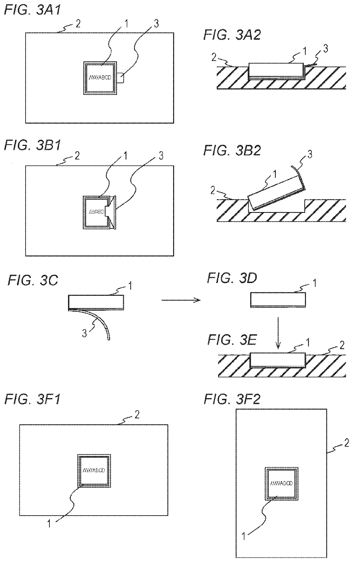
[0033]Next, as illustrated in FIG. 1B, an equipment body 2 is included in electronic equipment, such as an audio power amplifier. A recess 21 that is hollow for insertion of the logo plate 1, is provided on one face of the housing of the equipment body 2.

[0034]Here, the recess 21 has a shape into which the logo plate 1 can be inserted at least in either portrait orientation or landscape orientation. That is, in the illustrated example, both of the shape in the front, rear, left, and right directions ...


PUM


Abstract

Provided is a logo-plate component including a release sheet attached to the bottom face of a logo plate having an adhesive layer on the bottom face, the release sheet being provided with a cut-away portion exposing a part of the bottom face of the adhesive layer. Equipment is shipped with the logo-plate component temporarily fixed to an equipment body by the adhesive force of the exposed portion of the adhesive layer inside the cut-away portion of the release sheet. A user for the equipment detaches the temporarily fixed logo-plate component from the equipment body, detaches the release sheet from the logo plate, and fixes the logo plate to the equipment body in a desired orientation with the adhesive layer on the back face of the logo plate.

Description

RELATED APPLICATIONS[0001]The present application claims priority to Japanese Patent Application Number 2018-094489, filed May 16, 2018, the entirety of which is hereby incorporated by reference.BACKGROUND1. Field[0002]The present disclosure relates to a technique of fixing a display object to equipment.2. Description of the Related Art[0003]When fixing a display object, such as a logo plate, to equipment, there is a known technique of coupling a display object rotatably to equipment such that the display object can be made correct in position regardless of a mode of use of the vertical orientation / horizontal orientation of the equipment (e.g., JP 2014-13896 A).SUMMARY[0004]The above technique of fixing a display object rotatably to equipment requires that a display object or equipment is provided with a particular structure or mechanism enabling the display object to rotate relative to the equipment.[0005]Meanwhile, as a method of fixing a display object to equipment, fixing a disp...

Claims


Application Information

Patent Timeline
IPC IPC(8): G09F13/04G09F7/18
CPCG09F2007/1882G09F7/18G09F13/04G09F25/00G09F2003/0222
Inventor AIMI, SATORU
Owner ALPINE ELECTRONICS INC
Why Eureka
Try Eureka