Wax capsule and waxing device for a runner that glides over snow

Inactive Publication Date: 2019-11-28
LENDENMANN URS
0 Cites 0 Cited by

AI-Extracted Technical Summary

Problems solved by technology

There is a risk of burns, as the person applying hot wax to the ski must hold the solid wax block 50 in contact with the heating surface 35 of the iron 30.
Furthermore, such hot waxing sets usually require a dedicated workspace and are not easily transportable.
This is because hot wax is apt to adhere to the workbench 10, the iron 30 and other tools over the course of applying the hot wax, which can cause a mess and be difficult to remove.
Because t...

Method used

[0047]The handle 210 is shown as being generally cylindrical. In alternative embodiments, the handle 210 may take other forms, such as a prism, a generally L-shaped or U-shaped bar, or any other suitable shape. The handle 210 is preferably dimensioned so as to be comfortably held in a user's hand. The handle 210 may be made of a material such as a plastic or resin, or any other material that has sufficient structural stability to support the weight of the device 200. Preferably, the material of the handle 210 is insulative so as to protect a user gripping the handle 210 from heat generated in a space near the capsule containing portion 230. A surface of the handle 210 may be provided with a coating that provides a better grip to a user. Alternatively or in addition, a surface of the handle 210 may be formed with nubs, ridges or other structures to enhance the grip and/or reduce slipping between the handle 210 and a user's hand. The handle 210 may be formed with a hollow portion, such that an interior of the handle 210 is sufficient to accommodate some or all of the electronics that are used to power, monitor and control the device 200. The handle 210 may be conjoined with a battery receptacle or power cable (not shown) so as to provi...

Benefits of technology

[0026]According to a further aspect, a waxing device is suggested, further comprising a controller for controlling the energy supplied to the heat conduction means of the capsule depending on a sensed temperature or humidity received from the capsule and/or based on the identification of the capsule. This can simplify operation of the device and reduce errors by reducing user involvement in setting the operating temperature.
[0027]According to a further aspect, a waxing device is suggested, further comprising an interface comprising: a display for displaying a status of the waxing device, and/or a port for connecting the waxing device to another computing device. This can promote usability of the device.
[0028]According to a further aspect, a waxing device is suggested, further comprising an energy input for connecting the waxing device to an energy source. This can reduce the overall size and weight of the device, as no on-board energy supply is required in this case.
[0029]According to a further aspect, a waxing device is suggested, comprising at least one sensor selected from the following: a tempe...

Abstract

A capsule for containing wax to be applied to a surface of a runner that is adapted to glide over snow, and to a waxing device including the capsule. The capsule includes a compartment for containing wax and heat conduction device for heating the wax to a melting temperature. The compartment includes an application surface that is permeable or perforated or adapted to be perforated, to allow molten wax to exit the compartment via one or more perforations or pores, to apply the molten wax to the surface of the runner.

Application Domain

Snowboard bindingsSkis

Technology Topic

Wax removalMelting temperature +3

Image

  • Wax capsule and waxing device for a runner that glides over snow
  • Wax capsule and waxing device for a runner that glides over snow
  • Wax capsule and waxing device for a runner that glides over snow

Examples

  • Experimental program(1)

Example

[0045]In the following, the invention will be explained in more detail with reference to the accompanying figures. In the Figures, like elements are denoted by identical reference numerals and repeated description thereof may be omitted in order to avoid redundancies.
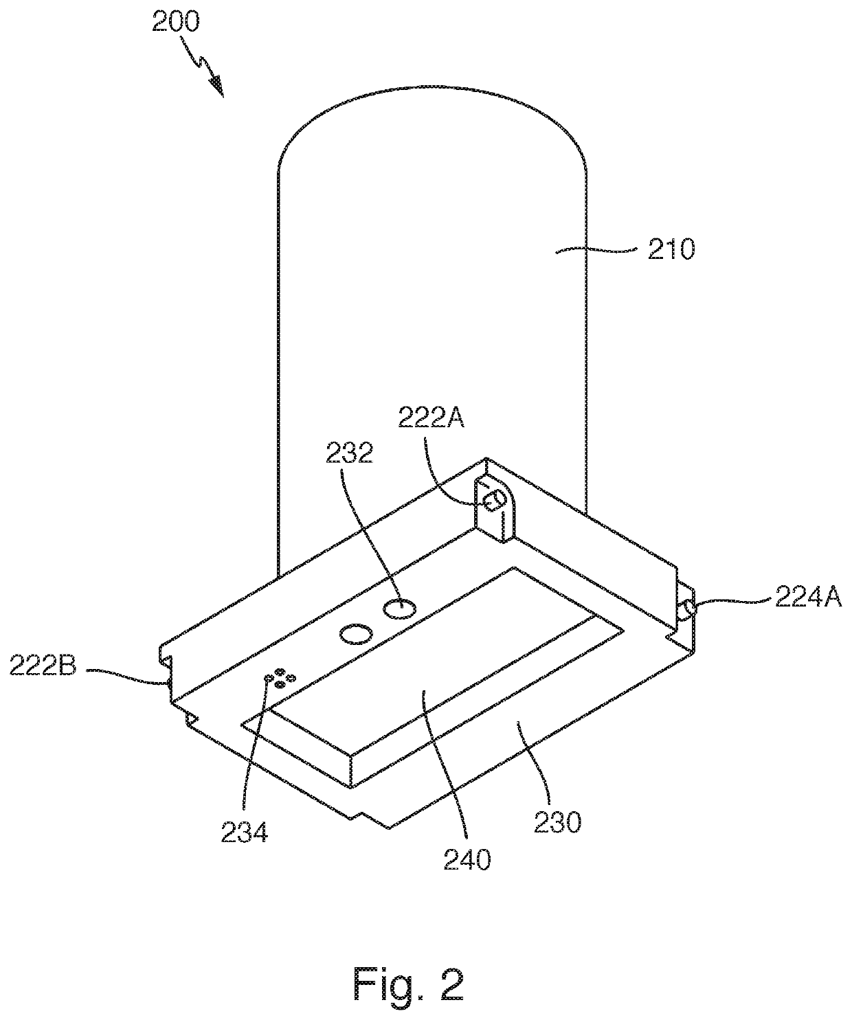
[0046]In FIG. 2, a waxing device 200 is shown. The waxing device comprises a handle 210 and a capsule containing portion 230.
[0047]The handle 210 is shown as being generally cylindrical. In alternative embodiments, the handle 210 may take other forms, such as a prism, a generally L-shaped or U-shaped bar, or any other suitable shape. The handle 210 is preferably dimensioned so as to be comfortably held in a user's hand. The handle 210 may be made of a material such as a plastic or resin, or any other material that has sufficient structural stability to support the weight of the device 200. Preferably, the material of the handle 210 is insulative so as to protect a user gripping the handle 210 from heat generated in a space near the capsule containing portion 230. A surface of the handle 210 may be provided with a coating that provides a better grip to a user. Alternatively or in addition, a surface of the handle 210 may be formed with nubs, ridges or other structures to enhance the grip and/or reduce slipping between the handle 210 and a user's hand. The handle 210 may be formed with a hollow portion, such that an interior of the handle 210 is sufficient to accommodate some or all of the electronics that are used to power, monitor and control the device 200. The handle 210 may be conjoined with a battery receptacle or power cable (not shown) so as to provide power to the waxing device 200.
[0048]As described in more detail in the following paragraphs, the capsule containing portion 230 serves the purpose of accommodating a wax capsule (described below with respect to FIG. 4), as well as providing interfaces for power connections and/or data connections between the waxing device 200 and the wax capsule. Furthermore, the capsule containing portion 230 comprises means for attaching a frame (described below with respect to FIG. 3) that is used to immobilize the wax capsule with respect to the waxing device 200.
[0049]Specifically, the capsule containing portion 230 comprises a recess 240 for accommodating an upper portion of a wax capsule. The recess 240 is in the shape of a rectangular prism and is preferably dimensioned to correspond to outer dimensions of the wax capsule. In alternative embodiments, the shape of the recess 240 may take other forms: for example, the recess 240 may be circular, irregular, and/or have one or more curved or beveled edges. In some cases, the recess 240 may not be provided at all; in other words, the capsule containing portion 230 may have a flat or convex outer surface. In any case, the outer surface of the capsule containing portion 230 and in particular the recess 240 should correspond in form to the outer dimensions of the wax capsule.
[0050]In some embodiments, a surface of the recess 240 may be provided with springs or other biasing means (not shown) to cause a surface of the recess 240 to press against a wax capsule when a wax capsule is inserted into the waxing device 200. These springs or other biasing means may be provided in an interior of the capsule containing portion 230 and may extend into the handle 210. The springs or other biasing means may provide a constant force against the capsule, or they may provide a force that varies with a displacement of the surface of the recess 240. The spring force may be delivered to the wax via one or more wall enclosing the capsule; or, alternatively, the spring force may be applied to the wax—in solid or molten state—directly. In any case, the amount of spring force should be chosen such that wax in a molten state will exit the capsule, whereas wax in a solid state will remain within the capsule.
[0051]The capsule containing portion 230 also comprises an energy supply interface 232 for supplying energy in the form of electricity or thermal heat to the capsule, and data connections 234. In some embodiments, the energy supply interface 232 and data connections 234 may be provided in common via shared pins or ports. The energy supply interface 232 may be a solid interface or may include fluid transfer means to supply heat to the capsule.
[0052]Furthermore, the capsule containing portion 230 comprises hinge pins 222A, 222B and latching pins 224A (latching pin 224B not shown) to enable attachment of a frame 250 as shown in FIG. 3.
[0053]The frame 250 comprises hinge knuckles 252A, 252B for surrounding the hinge pins 222A, 222B, allowing the frame 250 to swing about an axis defined by hinge pins 222A, 222B. Furthermore, the frame 250 comprises latching hooks 254A, 254B that can latch onto latching pins 224A (and 224B, not shown) when the frame 250 is flush with the outer surface of capsule containing portion 230.
[0054]Instead of hinge pins 222A, 222B and hinge knuckles 224A, 224B, other known hinge means may be provided to removably or non-removably attach frame 250 to the waxing device 200. For example, an adhesive strip with a flexible band or stripe may be provided as part of frame 250 or device 200 to provide a hinged connection between these parts. Instead of adhesive, screws or nails or other fixing means may be used as part of the hinged connection between frame 250 and device 200. Furthermore, the frame 250 may be entirely removable from device 200, that is, without any hinge function. In yet another possible alternative, the frame 250 may be provided integrally with the waxing device 200, with a slot provided for insertion/removal of wax capsules. Such a slot may be covered or uncovered.
[0055]In the embodiment of FIG. 3, the frame 250 comprises a recess 260 for accommodating a lower portion of the wax capsule. The recess 260 is in the shape of a rectangular prism and is preferably dimensioned to correspond to outer dimensions of the wax capsule. In alternative embodiments, the shape of the recess 260 may take other forms: for example, the recess 260 may be circular, irregular, and/or have one or more curved or beveled edges. In any case, the surface of the recess 260 should correspond in form to the outer dimensions of the wax capsule.
[0056]In FIG. 3, the lower part of the recess 260 is completely open; in other words, the recess 260 constitutes a rectangular cutout or hole within frame 250. In alternative embodiments, a lower surface of the recess 260 may be partially covered or masked, for example to provide more structural stability when holding a wax capsule sandwiched between the waxing device 200 and the frame 250. In still other embodiments, the lower surface of the recess 260 may be covered except for one or more slits or perforations, which would allow molten wax to exit the wax capsule through the recess 260. In any case, the recess 260 should be formed in such a way that there is at least one path for molten wax to exit.
[0057]The frame 250 comprises notches 270A, 270B which are used for alignment of the wax capsule within the frame 250, and relative to the waxing device 200, as described in more detail below.
[0058]FIGS. 4A4B and 4C show an embodiment of a wax capsule 100. The wax capsule 100 comprises a wax compartment with an upper portion 140 and a lower portion 160 for containing a wax block (50, not shown). Along a perimeter of the wax capsule 100, a ledge 130 is provided for interface and alignment purposes, with respect to the waxing device 200.
[0059]As mentioned previously, the upper portion 140 of the wax compartment corresponds in size and shape to the recess 240 provided in the waxing device, and the lower portion 160 of the wax compartment corresponds in size and shape to the recess 260 in the frame 250. An overall size of the wax compartment, defined as a total volume enclosed by the upper portion 140 and the lower portion 160, is preferably suited to contain a single application of wax. In other words, an amount of wax contained within the wax compartment may be sufficient for a single application of hot wax to a pair of skis or to a snowboard. In alternative embodiments, the wax compartment may be larger, to allow two or more applications of wax from a single capsule. An upper limit of the size of the wax compartment is bounded only by overall considerations regarding size and weight of the waxing device 200 containing a fully loaded capsule 100: the device 200 should in any case be small and light enough to operate by a person, preferably using one hand. In principle, a capsule 100 containing enough wax for hot wax applications to multiple or even dozens of pairs of skis is conceivable.
[0060]The ledge 130 comprises an energy supply interface 132 for receiving energy supplied from the waxing device in the form of electricity or thermal heat. The ledge 130 also comprises data connections 134. In some embodiments, the energy supply interface 132 and data connections 134 may be provided in common via shared pins or ports. The energy supply interface 132 may be a solid interface or may include fluid transfer means to supply heat to the capsule 100.
[0061]In alternative embodiments, energy or heating means may be provided directly within the capsule 100, for example as a single-use or rechargeable battery or as a single-use or reusable chemical heat pack. In this case, no energy supply interfaces 232, 132 are necessary.
[0062]In alternative embodiments, no data is exchanged between the capsule 100 and the waxing device 200, for example because any sensors used to control operation of the waxing device 200 are provided exclusively within the waxing device 200 and/or within the frame 250, but not within the capsule 100. In these cases, no data connections 234, 134 between the waxing device 200 and the capsule 100 are necessary.
[0063]The ledge 130 comprises notched recesses 170A, 170B that correspond in position and size to notches 270A, 270B of the frame 250. Instead of notches, other alignment means as known in the art can be provided, such as pins, tabs, or other designs with form-fitting means to promote alignment. Furthermore, the notches 270A, 270B need not be provided on the frame 250, but can instead be provided within recess 240 or on a lower surface of the capsule containing portion 230 of the waxing device 200 itself.
[0064]In alternative embodiments, the ledge 130 may be provided at a position such that the upper and lower portions 140, 160 of the wax compartment are of approximately equal volume. However, the ledge 130 may also be provided at a different height, so that the upper portion 140 is more voluminous than the lower portion 160, or vice versa. The ledge may be provided so high or so low that either the upper or lower portion 140, 160 is omitted entirely.
[0065]In some embodiments, the upper portion 140 of the capsule 100 may be made of a flexible material so as to allow springs or biasing means that are provided within the recess 240 of the waxing device 200 to compress the volume of the wax compartment. This can speed the exit of molten wax from the compartment.
[0066]In alternative embodiments, the ledge 130 may not surround the entire perimeter of the capsule 100, but instead may be provided on only one or more sides of the capsule 100.
[0067]In alternative embodiments, interface means (including energy supply interface and data connection) and alignment means (such as notches) may be provided directly on the wax compartment—either on the upper portion 140 or on the lower portion 160—rather than on the ledge 130. Preferably, the interface means are provided at a location that they cannot be inadvertently touched by a user when the waxing device 200 is in operation.
[0068]The lower portion 160 of the wax compartment comprises an application surface 162 which is in proximity or in contact with the surface of a ski or the like when hot wax is being applied to the ski or the like. The application surface 162 comprises heat conductors 164 and perforations 166 for allowing molten wax to exit the wax compartment.
[0069]The application surface 162 has a rectangular shape and covers substantially the entire lower surface of the lower portion 160 of the capsule 100. However, in alternative embodiments, the application surface 162 may cover less than the entire surface, and may take a form other than the rectangular form shown (such as circular or irregular). The application surface 162 is shown in FIG. 4B as being a single contiguous surface, but in alternative embodiments the application surface 162 may comprise two or more surfaces, of the same or different shapes or sizes, that are disjoint or only partially joined. In one preferred embodiment, the application surface 162 may be dimensioned to substantially match the width of the ski to which wax is to be applied.
[0070]Before the first use of a capsule 100, the application surface 162 may be covered with a foil or reusable cover. In this case, when a capsule 100 is selected, then before it is inserted into the waxing device 200, the foil or reusable cover is first manually removed to expose at least a portion of the application surface 162. In alternative embodiments, the waxing device 200 may include puncturing means such as pins or blades for puncturing the foil or cover when a capsule 100 is inserted into the device 200, so as to expose at least a portion of the application surface 162. In this case, the foil or cover is non-reusable. However, in case the capsule 100 is equipped with a reusable cover, the reusable cover can be applied after hot wax application when the capsule 100 is removed from the waxing device 200.
[0071]As shown in FIG. 4B, the application surface 162 comprises heat conductors 164 which may be made of nichrome wire or similar, which convert electrical energy into heat. The heat conductors 164 are provided in parallel at equal intervals, and are separated by lines of perforations 166. Alternative embodiments should contain at least one heat conductor 164, but may contain more, which may be separated by larger or smaller intervals, or may be provided at irregular intervals. Furthermore, the heat conductors 164 may take other shapes such as wavy or zig-zag lines, wider lines such as strips or bands, and/or surfaces such as plates. Furthermore, or the heat conductors 164 may be provided in a lattice or other patterns rather than in parallel lines.
[0072]The one or more heat conductors 164 may function by transforming electrical energy into thermal energy so as to heat wax that is contained within the wax compartment. Alternatively, the heat conductors 164 may be conduits containing fluid which is heated within another part of the capsule 100 or within the waxing device 200. In yet another alternative, the heat conductors 164 may be made of a material with a high thermal conductivity, such that a heat source applied at one end of a heat conductor 164 is conducted throughout the entire heat conductor so as to heat the wax.
[0073]The one or more heat conductors 164 may be provided on an outer surface of the lower portion 160 of the wax compartment. In alternative embodiments, the heat conductors may be provided within the application surface 162 or on an inner surface of the wax compartment, either along the inner surface of the lower portion 160 or elsewhere. Preferably, the heat conductors 164 should be provided in a vicinity of the wax block 50 so as to cause the wax block 50 to at least partially melt, when the heat conductors 164 provide heat.
[0074]In the embodiment of FIG. 4B, perforations 166 (which may also be called pores) are provided as rows of circular cutouts between each of the heat conductors 164. In alternative embodiments, the perforations 166 may have a different shape, such as a slot-shape whose length is similar or equal to the length of the heat conductors 164. In other alternative embodiments, larger or smaller perforations 166 may be used. In general, the number, size, shape, and placement of the perforations 166 may be chosen in any way, as long as molten wax can exit the compartment through one or more perforations 166.
[0075]In alternative embodiments, the capsule 100 may be provided without any perforations 166 at all, or with predetermined breaking points delineating future perforations 166, or with perforations 166 that are initially covered by a protective foil or plastic layer. Before a first use of the capsule 100, perforations 166 may then be punctured (either manually using a separate tool or automatically using puncturing means provided in the waxing device 200) or exposed (e.g. by removing the foil cover).
[0076]In other alternative embodiments, in addition to or instead of providing perforations 166 or predetermined breaking points for perforations 166, the application surface 162 may be covered with a permeable material such as a porous paper or felt. The permeable material contains pores or holes that allow wax to seep through when the wax is in a molten state, but contain the wax when it is in a solid state.
[0077]As shown in FIG. 4C, the wax capsule 100 may further comprise one or more wipers or lips 168A, 168B to sweep excess wax. A first wiper or lip 168A may be provided on an edge that follows behind the application surface 162 with respect to the direction of travel of the device 200 as it is moved over a ski or the like. A second wiper or lip 168B may be provided on the opposite edge of the application surface 162, in case the device 200 is moved in the opposite direction. The wipers 168A and/or 168B may stick out above the profile of the application surface 162 so as to collect excess wax. The wiper or lip 168 may be made of a flexible material such as rubber or silicone that preferably can withstand the temperatures of the molten wax without damage to its material properties.
[0078]FIG. 5 shows an assembly of the waxing device 200 containing a wax capsule 100. As shown in FIG. 5, the frame 250 is rotatably joined to the waxing device 200 by means of hinge pins 222A, 222B and corresponding hinge knuckles 252A, 252B. A wax capsule 100 is inserted between the waxing device 200 and frame 250 such that the application surface 162 of the capsule 100 extends into the recess 260 in the frame 250. Preferably, the capsule 100 is aligned with the frame 250 in such a way that the application surface 162 is partially or, better yet, fully exposed via the recess 260. Preferably, the application surface 162 extends slightly beyond a lower surface of the frame 250, so that when the application surface 162 is applied to a ski or the like, the lower surface of the frame 250 remains free of wax.
[0079]When the capsule 100 has been inserted and correctly aligned, the frame 250 is used to lock the capsule 100 in place with respect to the waxing device 200. This is done by rotating the frame 250 about the axis defined by hinge pins 222, until the latching hooks 254A, 254B of the frame 250 are in alignment with latching pin 224 of the waxing device 200. A latching mechanism 256 is then used to clamp the frame 250 in a closed position.
[0080]In the perspective shown in FIG. 5, an on/off switch 295 is visible on the capsule containing portion 230 of the device. In alternative embodiments, the switch 295 may be provided on the handle 210 or on the frame 250. In particular, the switch 295 may alternatively be located at a position on the waxing device 200 such that the switch 295 is automatically pressed as a result of a proximity between the waxing device 200 and the surface of the runner 20 to which wax is to be applied.
[0081]Although FIG. 5 shows a single bar as a latching mechanism 256, the latching mechanism can also be provided as a single lever or as two or more separate levers, e.g. with one lever for each latching pin/latching hook assembly. Alternatively, different types of latches known in the art may be used to immobilize the frame 250 with respect to the waxing device 200. In case the frame 250 is provided integrally with the waxing device 200, no latching mechanism 256 is necessary.
[0082]Although the embodiment of FIG. 4 shows wipers 168A, 168B as being provided on the wax capsule 100, in alternative embodiments one or more wipers or lips 168 may be provided, in addition or alternatively, on the frame 250 and/or on the waxing device 200. The wiper or lip 168 may stick out above the profile of the frame 250 and/or application surface 162 so as to collect excess wax.
[0083]FIG. 6 shows the electronics of the capsule 100 and of the waxing device 200 as a block diagram.
[0084]The capsule 100 shown in the embodiment of FIG. 6 comprises a microcontroller 180, a transceiver 182, a sensor 184, a memory 186, and electrical heat conductors 164. The microcontroller 180 controls the function of the transceiver 182, one or more sensors 184, memory 186 and electrical heat conductors 164.
[0085]It is contemplated that an alternative embodiment of the capsule 100 could be provided without any microcontroller 180, or with a controller in place of the microcontroller 180. In case no microcontroller 180 is provided, the electrical heat conductors 164 could be controlled directly by the waxing device 200. The transceiver 182 would then be superfluous. The rest of the electrical circuitry (including one or more sensors 184 and memory 186) could be omitted or controlled directly by the waxing device 200 via dedicated communication channels.
[0086]The transceiver 182 may be adapted to provide wireless communication or hardwired communication with the waxing device 200. This may allow the microcontroller 180 to receive information about a power level that should be used to drive electrical heat conductors 164 or to transmit information collected by one or more sensors 184.
[0087]The sensor 184 may comprise one or more sensors for sensing a temperature of the wax or of the wax compartment, for sensing a fill level of the wax within the wax compartment, for sensing a pressure within the wax compartment, and/or for sensing an ambient temperature or an ambient humidity. Sensed values may be used by controller 180 to adjust a power level of heat conductors 164. Alternatively or in addition, sensed values may be stored temporarily in memory 186 or communicated via controller 180 to transceiver 182, for transmission to the waxing device 200. The waxing device 200 may record a temperature profile and/or a fill profile over time, or may use the sensed values to communicate control instructions to the capsule 100 for adjusting a power level of heat conductors 164.
[0088]The memory 186 may store identification information for identifying the capsule 100. The identification information may comprise a serial number or a bit pattern that encodes information about the capsule 100. For example, the identification information may indicate which type of wax is contained in the capsule 100, for example by listing the name of the wax or a serial number corresponding to the type of wax. This may be plugged into a look-up table to ascertain further properties of the wax, such as its melting temperature and its preferred uses (e.g. what snow conditions and weather conditions it is adapted for). Alternatively, information about melting temperature and/or uses may also be stored as part of the identification information. The identification information may, alternatively or in addition, contain other information relating to the capsule 100, such as a width of the application surface 162. The identification information may be used to track how long a capsule 100 has been in use and may be associated with an estimate of an amount of wax left within the capsule 100.
[0089]In alternative embodiments, the identification information may be provided within an RFID tag in the capsule 100, or within a barcode or the like that is optically scannable. In this case, the waxing device may be provided with corresponding means for obtaining the identification information.
[0090]The waxing device 200 shown in the embodiment of FIG. 6 comprises a controller 280, a transceiver 282, a sensor 284, a display 286, and a power supply unit 288. The controller 280 controls the function of the transceiver 282, one or more sensors 284, display 286, power supply unit 288, and port 290.
[0091]It is contemplated that an alternative embodiment of the waxing device 200 could be provided without any controller 280, or with a microcontroller in place of the controller 280. It is also contemplated that some or all of these components could be provided within the frame 250 rather than in the waxing device 200. In case no controller 280 is provided, the electrical heat conductors 164 could be powered directly by the power supply unit 288. The transceiver 282, one or more sensors 284, display 286, and port 290 would then be superfluous, as well as most or all of the circuitry of the capsule 100.
[0092]The transceiver 282 may be adapted to provide wireless communication or hardwired communication with the capsule 100. This may allow the controller 280 to send information about a power level that should be used to drive electrical heat conductors 164, to receive information collected by one or more sensors 184 of the capsule 100, or to transmit information collected by one or more sensors 284 of the waxing device 200.
[0093]The sensor 284 may comprise one or more sensors for sensing a temperature of the wax or within the wax compartment, or for sensing an ambient temperature or an ambient humidity.
[0094]The display 286 may be a LCD or LED display, and may also be a touchscreen display (to enable inputs from a user to be received). In alternative embodiments, a user interface such as switches, control buttons, a mouse or even a keyboard may be used as an input device. The display 286 may indicate a status of the waxing device, a sensed temperature, a recommended operating parameter, or the like to a user.
[0095]The power supply unit 288 may comprise a standard AC input for collecting to an electric grid, as well as a transformer. Alternatively, the power supply unit 288 may comprise an interface with a DC power source or an on-board power source such as a battery. In yet another alternative, the power supply unit 288 may be omitted entirely if chemical rather than electrical means (such as a chemical hot pack) is used to supply heat to melt the wax.
[0096]The port 290 may be a USB port, wireless port (e.g. BlueTooth) or other standard communications port that enables the device 200 to connect to an external device such as a smartphone, laptop or other computing device. This may enable a selection of a wax capsule and/or temperature parameters when applying hot wax to be adjusted based on external data such as weather data and/or data on location or altitude. This may also enable data relating to the hot wax application to be exported, e.g. for performance tracking and analysis. In alternative embodiments, the port 290 may be omitted, so that the device 200 acts as a stand-alone device and does not communicate with external computing devices.
[0097]The transceiver 182 of the capsule 100 may communicate with the transceiver 282 of the waxing device 200 via a datalink 300, which may be a wireless link or a hardwired link, such as a standard communications port.
[0098]It will be obvious for a person skilled in the art that these embodiments and items only depict examples of a plurality of possibilities. Hence, the embodiments shown here should not be understood to form a limitation of these features and configurations. Any possible combination and configuration of the described features can be chosen according to the scope of the invention.
LIST OF REFERENCE NUMERALS
[0099]10 Workbench
[0100]15 Supports
[0101]20 Ski
[0102]30 Iron
[0103]35 Heating surface
[0104]50 Wax block
[0105]52 Molten wax
[0106]55 Wax layer
[0107]100 Capsule
[0108]130 Ledge
[0109]132 Energy supply interface
[0110]134 Data connection
[0111]140 Upper portion of wax compartment
[0112]160 Lower portion of wax compartment
[0113]162 Application surface
[0114]164 Heat conductors
[0115]166 Perforations
[0116]170A, 170B Notched recesses/alignment means
[0117]180 Microcontroller
[0118]182 Transceiver
[0119]184 Sensor
[0120]186 Memory
[0121]200 Waxing device
[0122]210 Handle
[0123]222A, 222B Hinge pins
[0124]224A Latching pin
[0125]230 Capsule containing portion
[0126]232 Energy supply interface
[0127]234 Data connection
[0128]240 Recess for upper portion
[0129]250 Frame
[0130]252A, 252B Hinge knuckles
[0131]254A, 254B Latching hooks
[0132]256 Latching mechanism
[0133]260 Recess for lower portion
[0134]270A, 270B Notches/complimentary alignment means
[0135]280 Controller
[0136]282 Transceiver
[0137]284 Sensor
[0138]286 Display
[0139]288 Power supply unit
[0140]290 Port
[0141]295 On/Off switch
[0142]300 Data link

PUM

no PUM

Description & Claims & Application Information

We can also present the details of the Description, Claims and Application information to help users get a comprehensive understanding of the technical details of the patent, such as background art, summary of invention, brief description of drawings, description of embodiments, and other original content. On the other hand, users can also determine the specific scope of protection of the technology through the list of claims; as well as understand the changes in the life cycle of the technology with the presentation of the patent timeline. Login to view more.

Similar technology patents

Method and apparatus for calibrating medical image data

ActiveUS20100290680A1reduce erroreasily calibrate and check
Owner:SIEMENS MEDICAL SOLUTIONS USA INC

Pseudolite navigation system

ActiveUS7142159B1provide flexibilityreduce error
Owner:ROCKWELL COLLINS INC

Multi-bit programming device and method of multi-bit programming

ActiveUS20080273405A1reduce error
Owner:SAMSUNG ELECTRONICS CO LTD

Classification and recommendation of technical efficacy words

Why Eureka
Try Eureka