Switching Arrangement and Transmission

a technology of switching arrangement and transmission, applied in the direction of mechanical actuated clutches, interengaging clutches, gearing, etc., can solve the problems of greater demands on the bearings of idler gears

Active Publication Date: 2019-11-28
ZF FRIEDRICHSHAFEN AG
View PDF0 Cites 1 Cited by
  • Summary
  • Abstract
  • Description
  • Claims
  • Application Information

AI Technical Summary

Benefits of technology

[0015]The guide of the coupling element, with respect to the first idler gear, has the effect that the coupling element is turned with respect to the first idler gear upon an axial displacement of the coupling element with respect to the first idler gear, due to the helical course of the guide. The coupling element likewise turns relative to the second idler gear after the engagement into the engagement geometry and the axial movement, which is still underway, into the coupling position. In a discrete axial position, the coupling element is rotationally fixed to the first idler gear via the guide, i.e., upon assumption of an axial position and in the absence of an axial movement toward the first idler gear, the first idler gear and the coupling element cannot be turned relative to each other. The same is the case with respect to the second idler gear after an engagement into the engagement geometry and an assumption of an axial position, due to the helical course of the engagement geometry, since a relative turning between the coupling element and the second idler gear is likewise prevented via the engagement geometry after an assumption of an axial position of the coupling element and the engagement of the coupling element.
[0016]According to one embodiment of the invention, pitches of running teeth of the idler gears, of the helically extending guide,

Problems solved by technology

In the case of a rotationally fixed coupling of idler gears of two spur gear stages, however, differential speeds with respect to the particular sha

Method used


Image

  • Switching Arrangement and Transmission
  • Switching Arrangement and Transmission
  • Switching Arrangement and Transmission

Examples


Embodiment Construction

[0031]Reference will now be made to embodiments of the invention, one or more examples of which are shown in the drawings. Each embodiment is provided by way of explanation of the invention, and not as a limitation of the invention. For example, features illustrated or described as part of one embodiment can be combined with another embodiment to yield still another embodiment. It is intended that the present invention include these and other modifications and variations to the embodiments described herein.

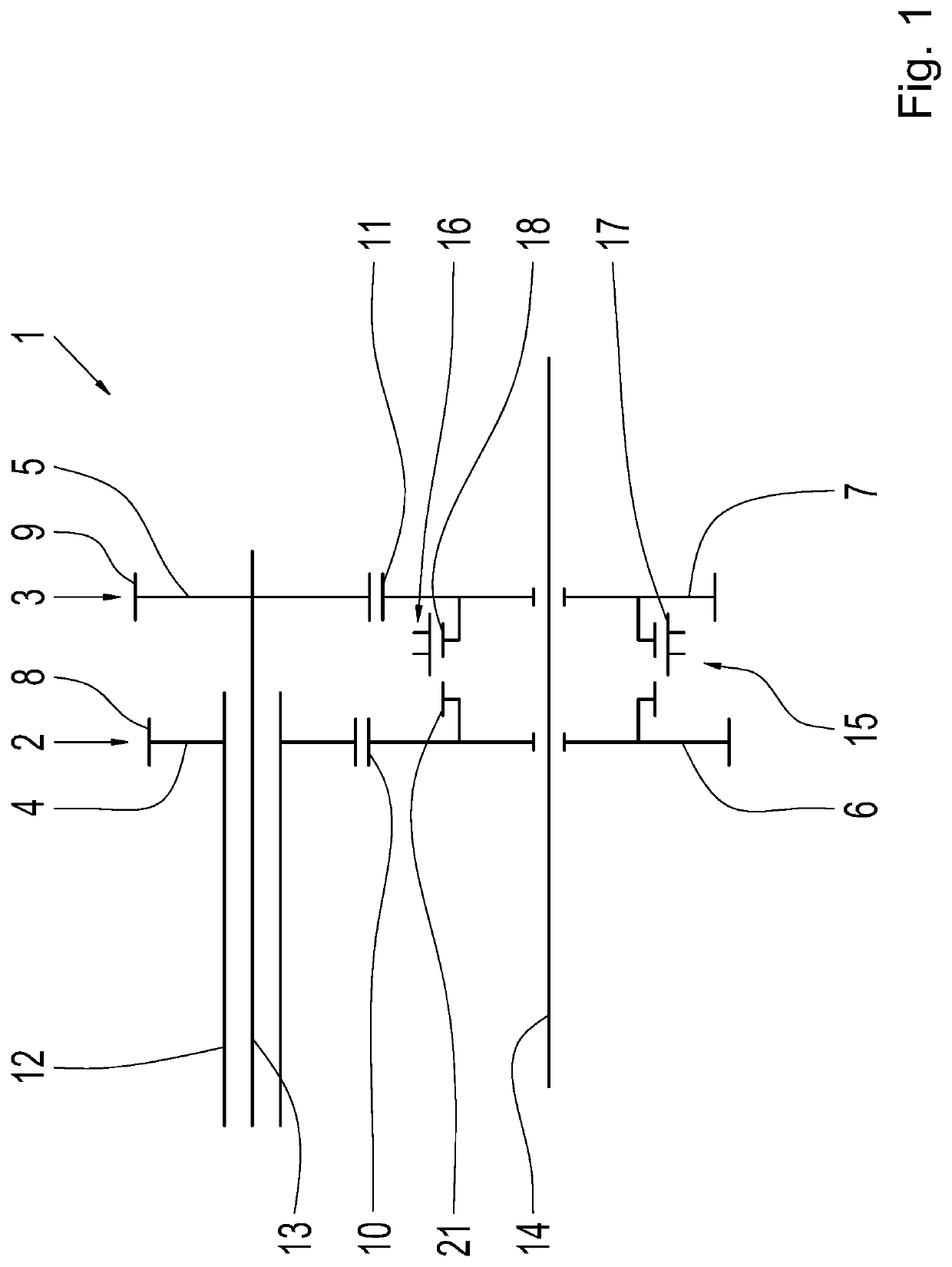
[0032]FIG. 1 shows a diagrammatic view of a part of a transmission 1, wherein the transmission 1 is represented in the area of two spur gear stages 2 and 3. The spur gear stages 2 and 3 are each composed of one first or fixed gear 4 and 5, respectively, and one second or idler gear 6 and 7, respectively, wherein the fixed gear 4 or 5 of the spur gear stage 2 or 3, respectively, is meshed, at a running tooth system 8 or 9, respectively, with a running tooth system 10 or 11, respect...


PUM


Abstract

A connecting arrangement includes first and second idler gears (6, 7) arranged coaxially and connectable via an engagement unit. The engagement unit includes a coupling element coupled to the first idler gear (7) in a direction of rotation and axially movable between a home position and a coupling position. In the coupling position, the coupling element is coupled to the second idler gear (6) in addition to being coupled to the first idler gear (7) in the direction of rotation. In the home position, the coupling element and the second idler gear (6) are freely turnable with respect to each other. The first and second idler gears (6, 7) are helical-cut spur gears. The coupling element is guided in a helically extending guide (18) on the first idler gear (7) and, in the coupling position, engages into a helically extending engagement geometry (21) on the second idler gear (6).

Description

FIELD OF THE INVENTION[0001]The invention relates generally to a connecting arrangement for the engageable coupling of two idler gears of a transmission, including a first idler gear and a second idler gear which are arranged coaxially to each other and are connectable to each other in a rotationally fixed manner via an engagement unit. The engagement unit includes a coupling element which is coupled to the first idler gear in the direction of rotation and is axially movable with respect to the first idler gear between a home position and a coupling position. The coupling element, in the coupling position, is also coupled to the second idler gear in addition to being coupled to the first idler gear in the direction of rotation, whereas, in the home position of the coupling element, the coupling element and the second idler gear are freely displaceable with respect to each other. Moreover, the invention relates generally to a transmission including an aforementioned connecting arrang...

Claims


Application Information

Patent Timeline
IPC IPC(8): F16D23/02F16D11/14
CPCF16H2063/3093F16D2011/002F16D11/14F16D23/02F16H63/30F16D23/00F16D11/00F16H3/006F16H2003/0807F16D11/10
Inventor REISCH, MATTHIASRIEGER, WOLFGANG
Owner ZF FRIEDRICHSHAFEN AG
Why Eureka
Try Eureka