Angular camshaft position adjustment drive

a technology of camshaft and position adjustment, which is applied in the direction of valve drives, machines/engines, and gearing, etc., can solve the problems of occupying a relatively large overall space, affecting the and not readily available, so as to achieve low efficiency of camshaft adjustment and facilitate control. control, the effect of simplifying the bearing

Inactive Publication Date: 2008-04-08
DAIMLER AG
View PDF19 Cites 4 Cited by
  • Summary
  • Abstract
  • Description
  • Claims
  • Application Information

AI Technical Summary

Benefits of technology

[0011]With the drive gear arrested, a negative gear ratio (speed-reducing mechanism) prevails between the first control input and the camshaft, and a positive gear ratio (speed-increasing mechanism) between the second control input and the camshaft, that is to say, in the case of a speed-reducing mechanism, the direction of rotation of the input is opposite to the direction rotation of the output, whereas in the case of a speed-increasing mechanism the direction of rotation remains the same. For maintaining a phase position constant, both control inputs can be operated at camshaft speed, which corresponds to a coupling with no relative movement in the mechanism. In the case of a self-locking mechanism between the drive gear and the camshaft no additional brake torque is needed for this purpose. If the mechanism is not self-locking, the same effect can be achieved through an additional brake torque, for example between two of the four shafts extending from the transmission or two parts rotating in opposition in adjustment sequences. In order to adjust the phase position, either of the two control inputs can be subjected to a brake torque, in particular a variable brake torque. The two control inputs are preferably connected to an electric drive motor, which preferably has coaxial shafts. If the first control input is braked on coupling, the camshaft will be advanced. The more lightly braked or entirely free-running second control input is in this case accelerated to a speed which is greater than the current camshaft speed. When the second control input is braked, the camshaft is retarded. The more lightly braked or entirely free-running first control input is in this case accelerated to a speed which is greater than the current camshaft speed. In both directions therefore rates of adjustment vary according to the gear ratio and the brake torque. Even a relatively low efficiency of such a transmission is acceptable. It has the advantages of a simplified bearing, and a tolerance in respect of a reduced gearing quality, and corresponding cost savings.
[0012]A simple adjusting mechanism construction results if a first gear train and a second gear train have planet wheels that can be driven at least indirectly by the drive gear.
[0015]In another embodiment, the first gear train comprises a planet gear supported on a first eccentric and the second gear train comprises a planet gear supported on a second eccentric. The first planet gear and the second planet gear can suitably be driven in parallel by an internal gear connected to the drive gear, which provides for an especially simple and compact construction. In an advantageous further embodiment the first planet gear can be brought into meshing engagement with a first internal ring gear and the second planet gear can be brought into meshing engagement with a second internal ring gear, the internal ring gears being rotationally locked to the camshaft.

Problems solved by technology

Such arrangements for adjusting the phase position usually take up a relatively large overall space, which is not readily available in modern vehicles accommodating numerous assemblies.
In order to adjust the phase position, use may be made, for example, of a hydraulic vane adjuster, the rate and angle of adjustment of which, however, are very limited.
At low engine speeds and low oil pressure, and when the vehicle is at standstill, the phase position cannot be adjusted.
Such an arrangement, however, entails high costs because of the highly geared two-stage transmission and the servomotor which are required.

Method used


Image

  • Angular camshaft position adjustment drive
  • Angular camshaft position adjustment drive
  • Angular camshaft position adjustment drive

Examples


Embodiment Construction

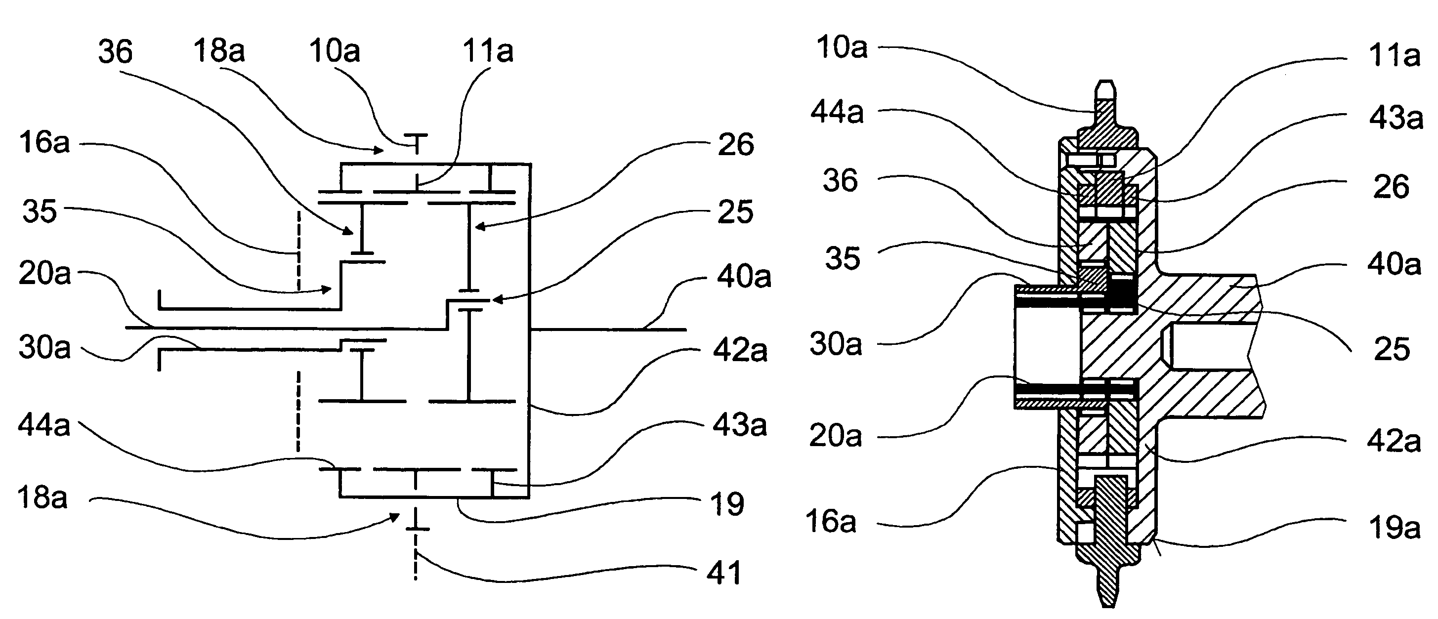
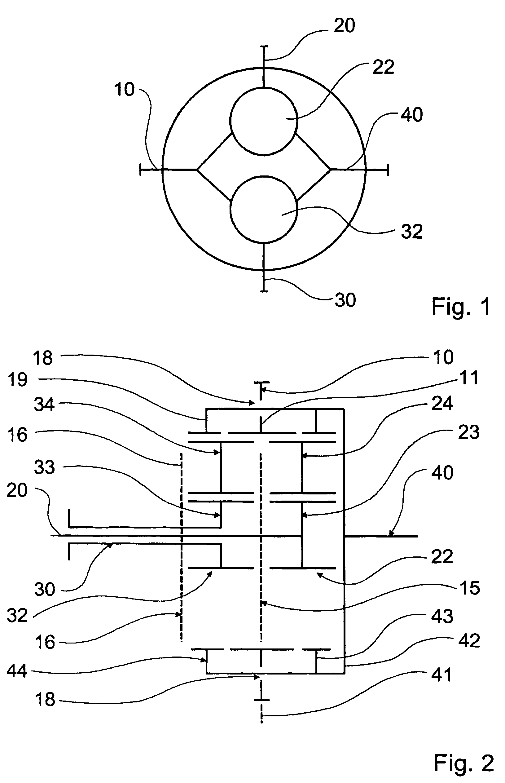
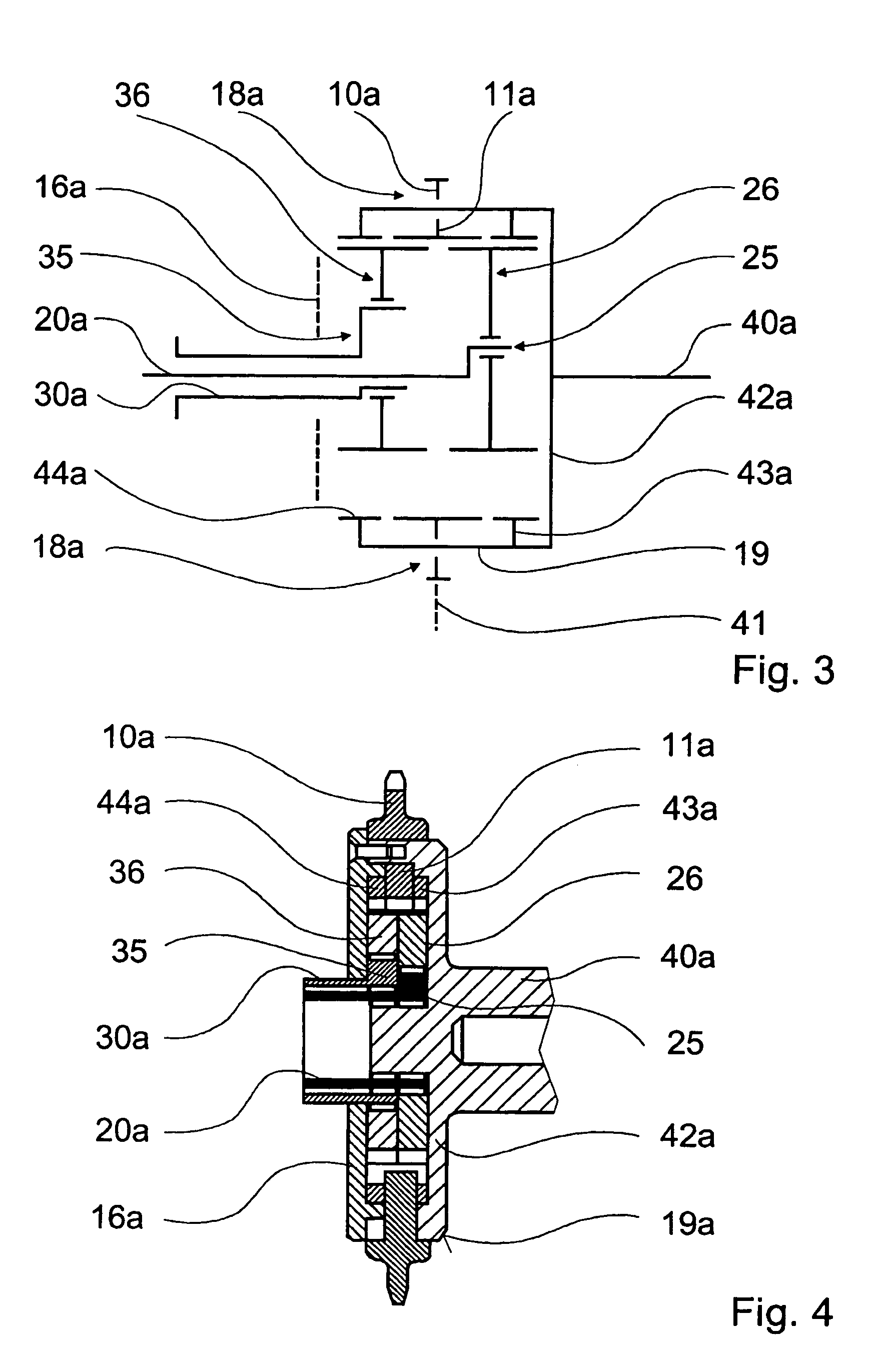
[0025]In the figures fundamentally identical or functionally similar parts are indicated by the same reference numerals.

[0026]FIG. 1 shows symbolically a preferred adjusting mechanism with a control device in the form of a four-shaft transmission for adjusting a phase position of a camshaft 40 in relation to a crankshaft (not shown) of an internal combustion engine (not shown), and with a drive gear 10 driven by the crankshaft for driving the camshaft 40.

[0027]Four shafts extend from the adjusting mechanism which comprises a drive gear 10, two control inputs with drive shafts 20, 30 and a transmission output, which is connected to the camshaft 40.

[0028]Each of the drive shafts 20, 30 of the control inputs acts on an associated gear train 22 and 32 respectively, designed as an epicyclic gear train. The two control inputs can be subjected to a drive and / or braking torque (brake torque).

[0029]The two gear trains 22, 32 in the form of epicyclic gear trains can in turn be designed as a c...


PUM


Abstract

In an adjusting mechanism having an adjusting device for adjusting a phase position of a camshaft in relation to a crankshaft of an internal combustion engine, and a drive gear driven by the crankshaft, for driving the camshaft, a four-shaft transmission configured as an epicyclic summing gear train for the adjustment of the phase position of the camshaft is provided in a housing from which four shafts extend and two of them are concentric for connection to corresponding shafts of a control motor capable of applying different braking torques to the two concentric shafts.

Description

[0001]This is a Continuation-In-Part Application of pending international patent application PCT / EP2005 / 003813 filed Apr. 4, 2005 and claiming the priority of German patent application 10 2004 018 942.0 filed Apr. 20, 2004.BACKGROUND OF THE INVENTION[0002]The invention relates to a camshaft adjusting mechanism for adjusting the phase position of a camshaft relative to a camshaft drive or crankshaft of an internal combustion engine.[0003]Variable valve timing in order to optimize the fuel consumption and engine power output in motor vehicles is already known. It is possible, for example, to adjust the phase position of a camshaft in relation to the crankshaft in order to vary the valve actuation. Such arrangements for adjusting the phase position usually take up a relatively large overall space, which is not readily available in modern vehicles accommodating numerous assemblies. In order to adjust the phase position, use may be made, for example, of a hydraulic vane adjuster, the rat...

Claims


Application Information

Patent Timeline
Patent Type & Authority Patents(United States)
IPC IPC(8): F01L1/34F01L1/344F01L1/352F16H35/00
CPCF01L1/344F01L1/352F16H35/008F01L2001/0473
Inventor GREGOR, MATHIASMEINTSCHEL, JENSSTOLK, THOMASVON GAISBERG-HELFENBERG, ALEXANDER
Owner DAIMLER AG
Why Eureka
Try Eureka