Blow-off valve

a blow-off valve and valve body technology, applied in valve housings, combustion air/fuel air treatment, machines/engines, etc., can solve the problems of marked deceleration of the turbocharger, the operation of the turbocharger, the precision so as to simplify the bearing of the pin and the piston, the effect of simplifying the assembly and improving the accuracy of the blow-off valv

Inactive Publication Date: 2018-05-10
CONTINENTAL AUTOMOTIVE GMBH
View PDF7 Cites 2 Cited by
  • Summary
  • Abstract
  • Description
  • Claims
  • Application Information

AI Technical Summary

Benefits of technology

[0007]It is therefore the object of the present invention to create a blow-off valve for use in a drive system having an internal combustion engine and having a turbocharger, which has a simplified bearing of the pin and the piston and therefore enables simpler assembly and more precise opening and closing of the blow-off valve.

Problems solved by technology

The build-up of dynamic pressure here may lead to a marked deceleration of the turbocharger, which is disadvantageous for the operation of the turbocharger.
A sudden opening of the throttle valve may also have a disadvantageous effect since an intense drop in pressure downstream of the turbocharger may occur, which may generate the so-called turbo lag.
Such dual bearings are, in particular, disadvantageous in that it is necessary to create at least two fits with narrow tolerances between the pin and the bearing elements.
The assembly of such a blow-off valve is very complex and the tolerance chain generated may result in particularly high tilt angles of the pin, whereby the functionality and, in particular, the precision of the blow-off valve are greatly impaired.

Method used


Image

  • Blow-off valve
  • Blow-off valve

Examples


Embodiment Construction

[0031]The following description of the preferred embodiment(s) is merely exemplary in nature and is in no way intended to limit the invention, its application, or uses.

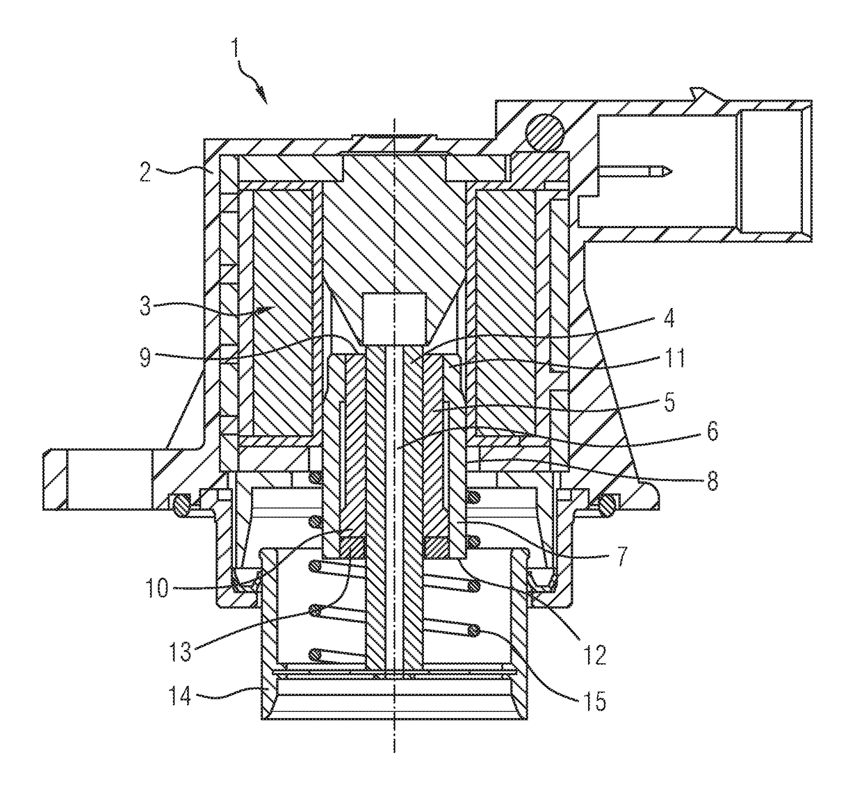
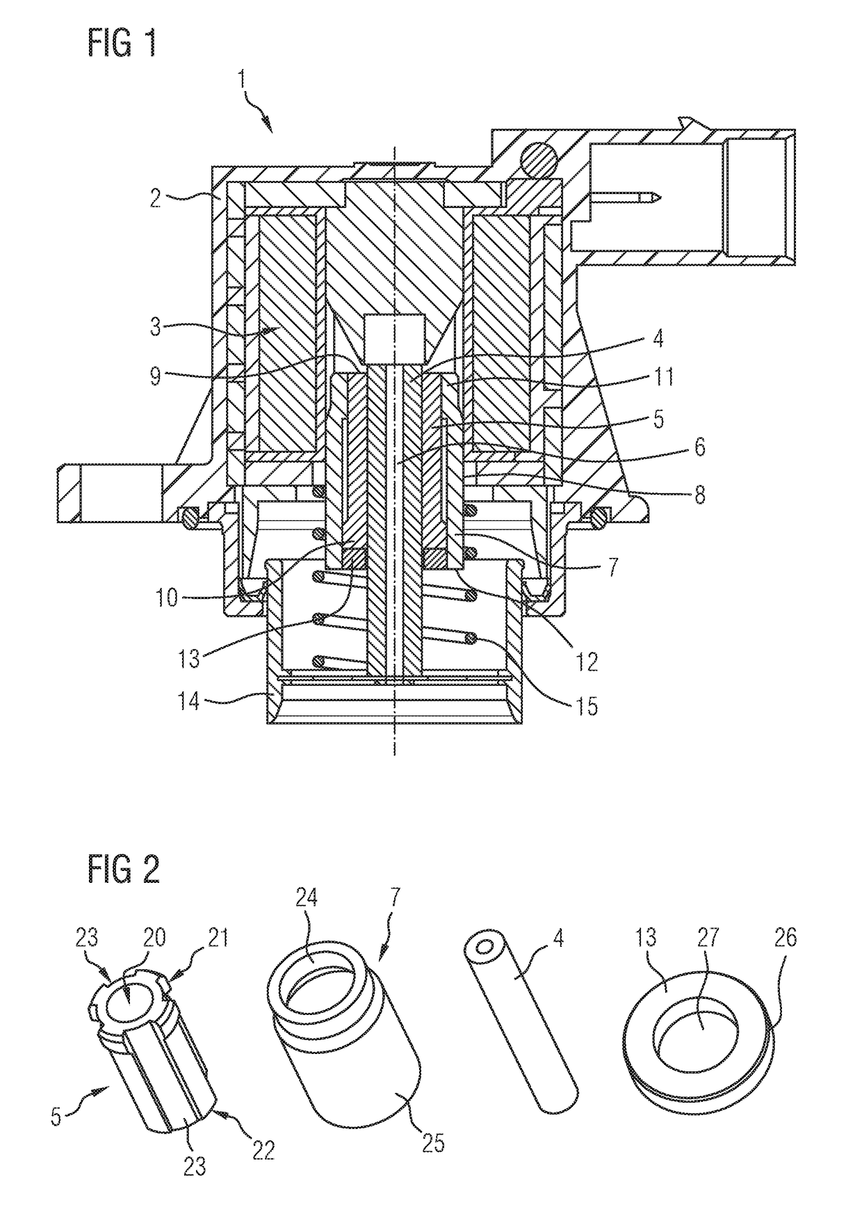
[0032]FIG. 1 shows a blow-off valve 1. The blow-off valve 1 has a housing 2 through which a flow may pass along a flow section. An electromagnet 3 is arranged in the housing 2, which electromagnet 3 is powered by a voltage source (not illustrated) whereby electromagnetic forces are produced, which act on the pin 4 arranged in the blow-off valve 1. The pin 4 is formed in the shape of a rod with a circular cross-section and has a central axial through-bore 6 extending through it in the exemplary embodiment of FIG. 1.

[0033]The pin 4 is guided in a sliding sleeve 5 and may be moved upward and downward relative to the sliding sleeve 5 in a translatory direction. The sliding sleeve 5 is formed as a tubular body and surrounds the pin 4 completely in the circumferential direction.

[0034]The sliding sleeve 5 is received in a be...


PUM


Abstract

A blow-off valve for controlling the pressure in an intake tract of an internal combustion engine, comprising a housing and a flow path formed in the housing, wherein the flow path is opened and/or closed by means of piston, which may be placed onto valve seat, wherein the piston is connected to a pin, which is moved by means of an electromagnetically producible force, wherein motion of the pin is transferred to the piston, wherein the support of the pin within the blow-off valve is realized by means of exactly one sliding sleeve, wherein the pin is moved in relation to the sliding sleeve.

Description

CROSS-REFERENCE TO RELATED APPLICATIONS[0001]This application claims the benefit of PCT Application PCT / EP2016 / 065588, filed Jul. 1, 2016, which claims priority to German Patent Application 10 2015 212 913.6, filed Jul. 9, 2015. The disclosures of the above applications are incorporated herein by reference.FIELD OF THE INVENTION[0002]The invention relates to a blow-off valve for regulating the pressure in an intake section of an internal combustion engine, having a housing and having a flow section formed in the housing, wherein the flow section is opened and / or closed by a piston which may be seated on a valve seat, wherein the piston is connected to a pin which is moved by means of an electromagnetically producible force, wherein a movement of the pin is transferred to the piston.BACKGROUND OF THE INVENTION[0003]In drive systems having an internal combustion engine and a turbocharger, so-called blow-off valves are used to prevent the generation of high dynamic pressures between th...

Claims


Application Information

Patent Timeline
Patent Type & Authority Applications(United States)
IPC IPC(8): F02M35/10F16K31/06
CPCF02M35/10236F16K31/0655F02M35/10157F02M35/10249F02B37/16F16K1/36F16K27/029F16K31/0648Y02T10/12
Inventor BONANNO, ROSARIO
Owner CONTINENTAL AUTOMOTIVE GMBH
Why Eureka
Try Eureka