Lens mount for viewfinder cameras

a technology for viewfinder cameras and lens mounts, applied in the direction of mountings, optics, instruments, etc., can solve the problems of reducing the design of the known lens mount is complicated, etc., to reduce the overall length of the lens mount, facilitate the mounting and simplify the bearing of the cam ring

Inactive Publication Date: 2006-05-16
LEICA GEOSYSTEMS AG
View PDF11 Cites 2 Cited by
  • Summary
  • Abstract
  • Description
  • Claims
  • Application Information

AI Technical Summary

Benefits of technology

[0007]It was therefore the object of the invention to simplify the bearing of the cam ring, to facilitate the mounting of the cam ring without influencing its drive elements, and to reduce the overall length of the lens mount.

Problems solved by technology

The known lens mount has a very complicated design.
Moreover, a greater overall length results for the lens mount because of the interposed plunger.

Method used


Image

  • Lens mount for viewfinder cameras
  • Lens mount for viewfinder cameras
  • Lens mount for viewfinder cameras

Examples


Embodiment Construction

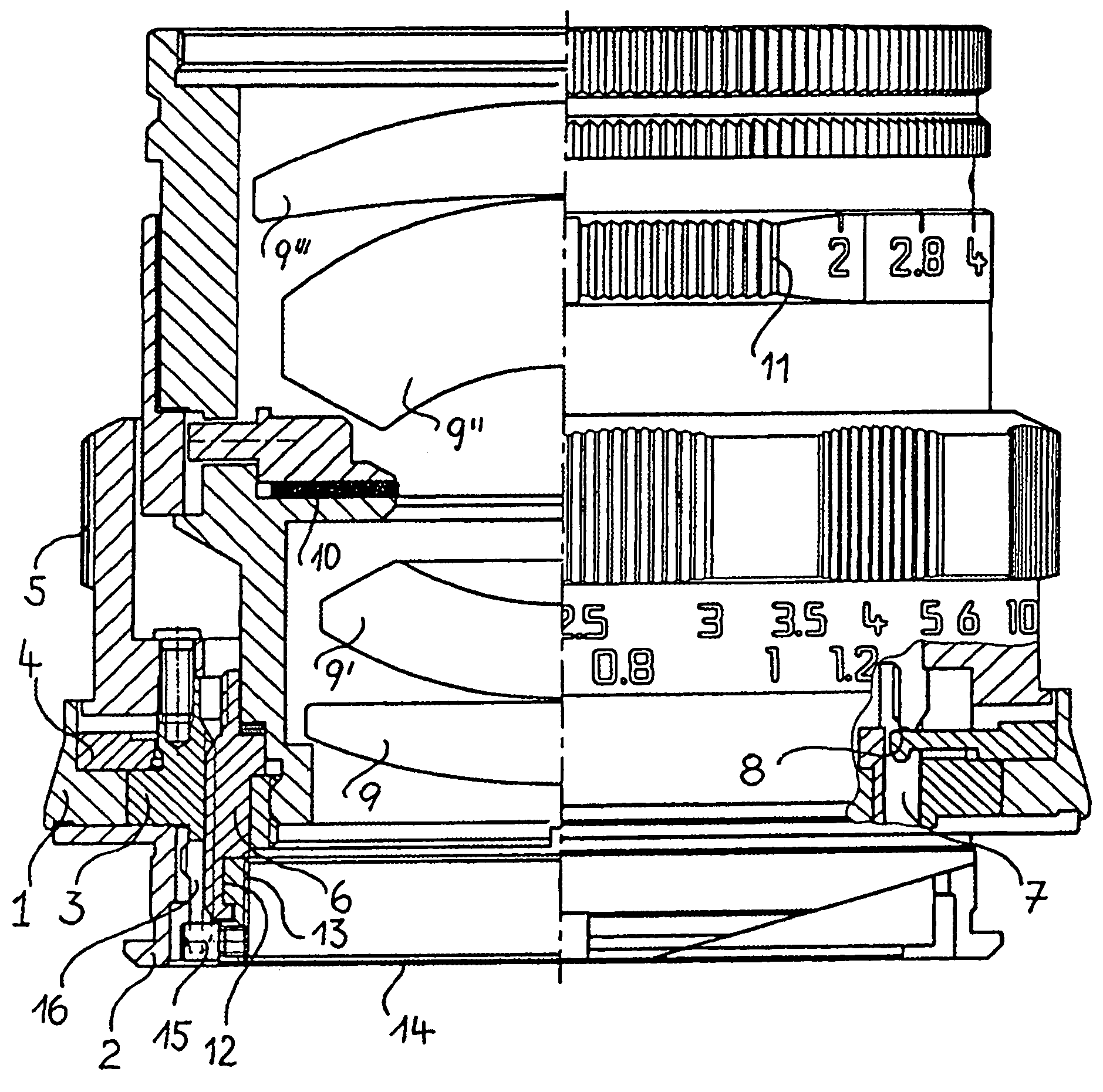
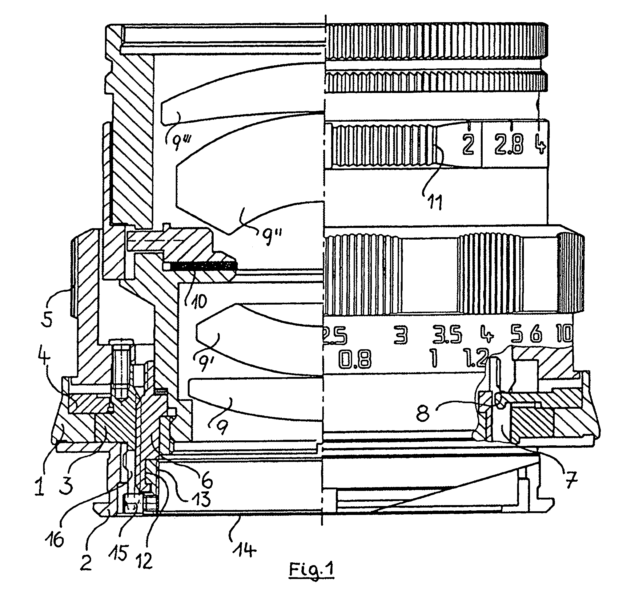
[0014]The lens mount illustrated in FIG. 1 comprises a basic body 1 which is connected to a bayonet ring 2. The bayonet ring 2 serves to lock the lens mount with a camera housing (not illustrated). An outer worm 3 is rotatably supported in the basic body 1. The outer worm 3 is held for this purpose on the underside of the bayonet ring 2 and on the upper side by an annular disc 4, likewise connected to the basic body 1.

[0015]The outer worm 3 is connected to a distance setting ring 5 such that the rotation thereof is transferred directly to the outer worm 3. The rotation of the distance setting ring 5 is limited by stops (not illustrated here) on the annular disc 4 for the permitted close-up focusing and for infinity focusing.

[0016]Inserted into the outer worm 3 is an inner worm 6 that is driven by the outer worm 3. The inner worm 6 has an axial groove 7 in which a nose 8 fitted on the annular disc 4 engages. The axial groove 7 and the nose 8 form a rectilinear guide for the inner wor...


PUM


Abstract

A lens mount for viewfinder cameras, having a distance setting ring and, coupled thereto, an apparatus for transmitting the set distance to the setting lever of a measuring viewfinder arranged on the camera side. The apparatus contains an outer worm connected to the distance setting ring, an inner worm, inserted in said outer worm and guided rectilinearly in the lens mount, and a cam ring rotatably supported in the inner worm and with an axial cam pointing to the camera on the end face, is characterized in that the cam ring is locked into an annular groove in the inner wall of the inner worm and is provided with preferably two pins which point radially outward over the edge of the inner worm at the end of the camera side, and which engage in each case in an axial groove in the outer worm.

Description

BACKGROUND OF THE INVENTION[0001]A lens mount is known from DE 2 040 227 A1. The lens mount includes several imaging lenses which can be displaced along the optical axis of the system by a distance setting ring in order in each case to image an object to be recorded sharply in the film plane. The distance setting ring is connected for this purpose to an outer threaded tube, designed as a worm, as drive apparatus. Inserted into this threaded tube is an inner threaded tube, which is likewise designed as a worm and is linearly guided in the lens mount such that the rotation of the outer threaded tube is converted into a displacement of the inner threaded tube along the optical axis of the system. The imaging lenses are inserted in a stationary fashion into the inner threaded tube and therefore participate in this longitudinal displacement.[0002]Moreover, a cam ring which is driven by a pilot pin connected to the outer threaded tube is inserted rotatably into the inner threaded tube on ...

Claims


Application Information

Patent Timeline
Patent Type & Authority Patents(United States)
IPC IPC(8): G02B7/02G02B7/04
CPCG02B7/04G02B7/023
Inventor DE WINTER, ANDRE
Owner LEICA GEOSYSTEMS AG
Why Eureka
Try Eureka