Vehicle Having a Transverse Leaf Spring Wheel Suspension

a transverse leaf spring and wheel suspension technology, applied in the direction of vehicle springs, resilient suspensions, interconnection systems, etc., can solve the problems of lower relationship between rolling and lifting rigidity, and generally complex inner articulation location structure, so as to prevent deterioration of dynamic vehicle behavior, low friction, and low hysteresis

Active Publication Date: 2014-06-26
FORD GLOBAL TECH LLC +1
View PDF11 Cites 1 Cited by
  • Summary
  • Abstract
  • Description
  • Claims
  • Application Information

AI Technical Summary

Benefits of technology

[0008]In order to prevent a deterioration of the dynamic vehicle behavior, the inner articulation locations are intended to be constructed with low friction and low hysteresis. Other objectives with regard to the construction of the inner articulation locations further include low costs, low weight, protection from contamination, the ability to resist high temperatures, moisture and chemical materials, etc., and taking into account spatial provisions.

Problems solved by technology

The structure of the inner articulation locations is generally rather complex since they must comply at the same time with various requirements.
In particular, a lower level of vertical rigidity leads to a lower relationship between rolling and lifting rigidity, which is, however, undesirable.

Method used


Image

  • Vehicle Having a Transverse Leaf Spring Wheel Suspension
  • Vehicle Having a Transverse Leaf Spring Wheel Suspension
  • Vehicle Having a Transverse Leaf Spring Wheel Suspension

Examples


first embodiment

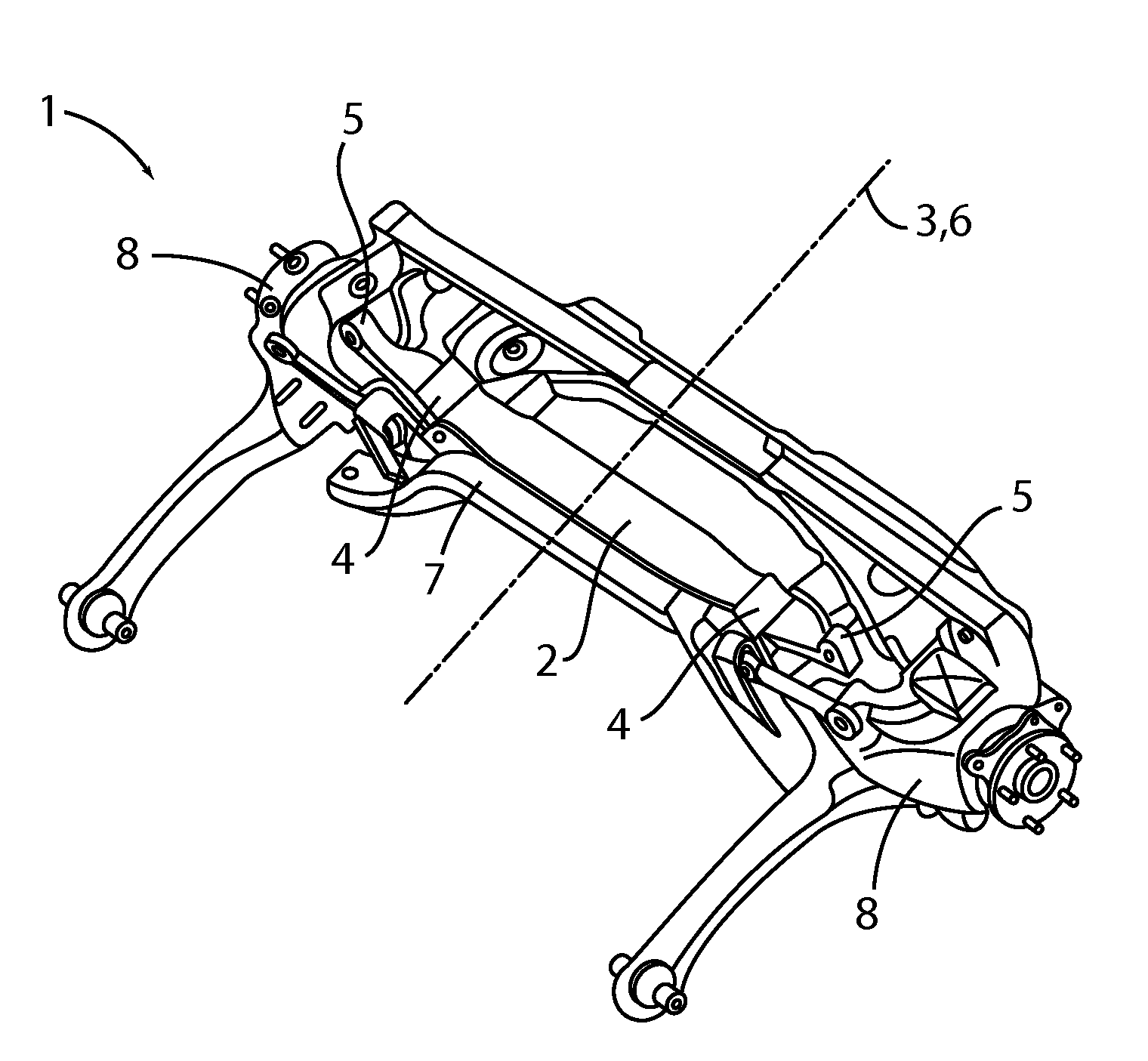
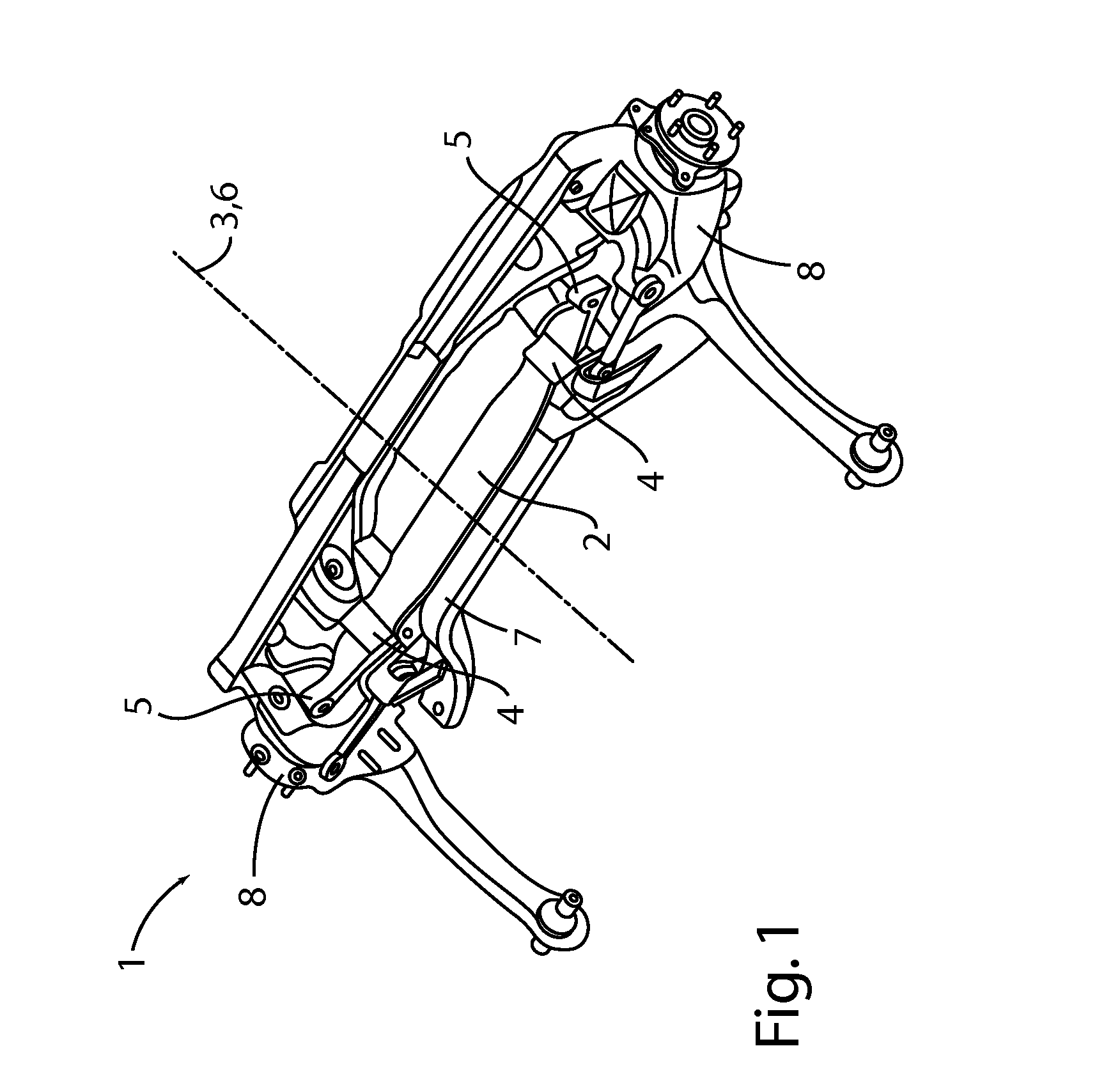
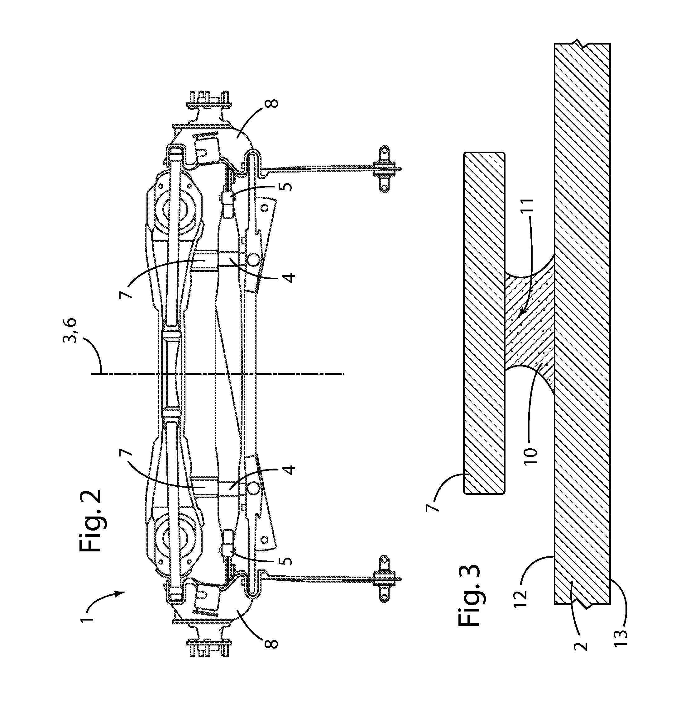
[0029]FIG. 1 is a perspective view from below of a wheel suspension 1 according to the invention having a transverse leaf spring 2 for an axle of a vehicle, in particular a motor vehicle. FIG. 2 is a bottom view of the same transverse leaf spring 2. The transverse leaf spring 2 which is preferably a transverse leaf spring produced from a composite glass-fiber material (composite transverse leaf spring) is arranged transversely relative to a vehicle longitudinal axis 3. As can be seen from FIGS. 1 and 2, the transverse leaf spring 2 has two inner, laterally spaced-apart articulation locations 4 or inner bearings 4 and two outer articulation locations 5 or outer bearings 5 at the free ends of the transverse leaf spring 2. The inner and outer articulation locations 4 and 5 are arranged at each of the two sides of a vehicle longitudinal center plane 6. The inner articulation locations 4 support the transverse leaf spring 2 on the vehicle superstructure or on an auxiliary frame 7 connect...

second embodiment

[0031]FIG. 4 is a schematic rear view of a wheel suspension 9 according to the invention having a transverse leaf spring 2 which is arranged transversely relative to a vehicle longitudinal axis 3. In one example the transverse leaf spring 2 can be made from a composite glass-fiber material (composite transverse leaf spring). As already described, the transverse leaf spring 2 is supported by two inner articulation locations 4 on the vehicle superstructure or on the auxiliary frame 7 which is connected to the vehicle superstructure. FIG. 4 additionally illustrates the transverse leaf spring 2 in two movement states, as can be assumed by the transverse leaf spring 2 during the travel operation.

[0032]FIG. 5 is an enlarged perspective view of an inner articulation location 4, including a resilient member 10 used with the transverse leaf spring 2 from FIG. 4. FIG. 6 is a sectioned view through the inner articulation location 4 of the transverse leaf spring 2 from FIG. 4. The inner articul...

third embodiment

[0036]FIGS. 7-9 illustrate a wheel suspension 15 according to the invention having a transverse leaf spring 2 arranged transversely relative to a vehicle longitudinal axis 3. The transverse leaf spring 2 can be made from a composite glass-fiber material (composite transverse leaf spring) illustrated schematically in FIG. 7 from the rear. Again, the transverse leaf spring 2 is supported by two inner articulation locations 4 on the vehicle superstructure or on the auxiliary frame 7 which is connected to the vehicle superstructure.

[0037]FIG. 8 is an enlarged perspective view of an inner articulation location 4 of the transverse leaf spring 2 of FIG. 7. FIG. 9 is a sectioned view through the same inner articulation location 4 of the transverse leaf spring 2 of FIG. 7. The inner articulation location 4 of the transverse leaf spring 2 of FIG. 7 includes a resilient member 16, for example, a rubber member, and a vehicle-side support 17. The vehicle-side support 17 is securely connected to ...


PUM


Abstract

The invention relates to a wheel suspension for a vehicle, in particular a motor vehicle, having a transverse leaf spring arranged transversely relative to a vehicle longitudinal axis. The transverse leaf spring is supported at each of the two sides of a vehicle longitudinal center plane by at least one resilient member on a vehicle-side support which is securely connected to the vehicle superstructure or an auxiliary frame which is connected to the vehicle superstructure. The resilient member and the support form an articulated engagement. With an articulated engagement provided at each side of the vehicle longitudinal center plane.

Description

CROSS-REFERENCE TO RELATED APPLICATIONS[0001]Not Applicable.BACKGROUND OF THE INVENTION[0002]1. Field of the Invention[0003]The present invention generally relates to a wheel suspension for a vehicle; and more specifically to a motor vehicle having a transverse leaf spring arranged transversely relative to a vehicle longitudinal axis.[0004]2. Description of Related Art[0005]Transverse leaf springs may be used in vehicle wheel suspensions as an efficient solution for weight reduction as they replace the superstructure springs and the stabilizer. In order to function as the superstructure springs and the stabilizer the leaf springs must be able to ensure, at the same time, a degree of rolling stability (resistance against mutually opposing vertical movement of the wheels) and a degree of lifting stability (resistance against vertical movement of the wheels in the same direction). Typically, these levels of rigidity are different. The transverse leaf spring, with a resiliently loaded m...

Claims


Application Information

Patent Timeline
Patent Type & Authority Applications(United States)
IPC IPC(8): B60G11/08
CPCB60G11/08B60G11/10B60G11/12B60G21/05B60G11/36B60G2202/114B60G2204/121B60G2206/428
Inventor GIRELLI CONSOLARO, ALBERTOSIMON, MARCZANDBERGEN, PAULGERHARDS, THOMASSHIMPL, WALTER
Owner FORD GLOBAL TECH LLC
Why Eureka
Try Eureka