Double row roller cam transmission mechanism with backlash adjustment means

a transmission mechanism and double row roller technology, applied in the direction of gearing, gearing elements, hoisting equipment, etc., can solve the problems of reducing the transmission efficiency and accuracy, reducing the service life of the cam, and easy to generate negative torque, so as to reduce the inertial load of the spiral protrusion, and eliminate the backlash

Active Publication Date: 2019-11-28
CHIU CHUI TSAI
View PDF0 Cites 6 Cited by
  • Summary
  • Abstract
  • Description
  • Claims
  • Application Information

AI Technical Summary

Benefits of technology

[0003]The present invention has been accomplished under the circumstances in view. It is therefore the main object of the present invention to provide a double row roller cam transmission mechanism with backlash adjustment means, which comprises two passive wheels respectively provided with rollers, a transmission shaft with a spiral protrusion, and an adjustment device set. The adjustment device set can be operated to adjust the relative position between the two passive wheels so that the rollers of the two passive wheels can be respectively and positively abutted against the two opposite surfaces of the spiral protrusion of the transmission shaft to eliminate the backlash between the rollers and the spiral protrusion, thereby reducing the inertial load of the spiral protrusion and increasing structural rigidity and transmission load.

Problems solved by technology

When the cam transmission mechanism is operated at high speed, the inertia load is large, so it is easy to generate negative torque.
If there is a backlash between the cam and the rollers, a knock will occur and vibration will be generated, reducing the transmission efficiency and accuracy and shortening the service life of the cam.
Due to the presence of the shaft coupling between the two cam members, adjusting the backlash becomes more difficult.
Further, the use of two cam members relatively increases the inertial load of the cam and shortens the service life of the cam.

Method used


Image

  • Double row roller cam transmission mechanism with backlash adjustment means
  • Double row roller cam transmission mechanism with backlash adjustment means
  • Double row roller cam transmission mechanism with backlash adjustment means

Examples


Embodiment Construction

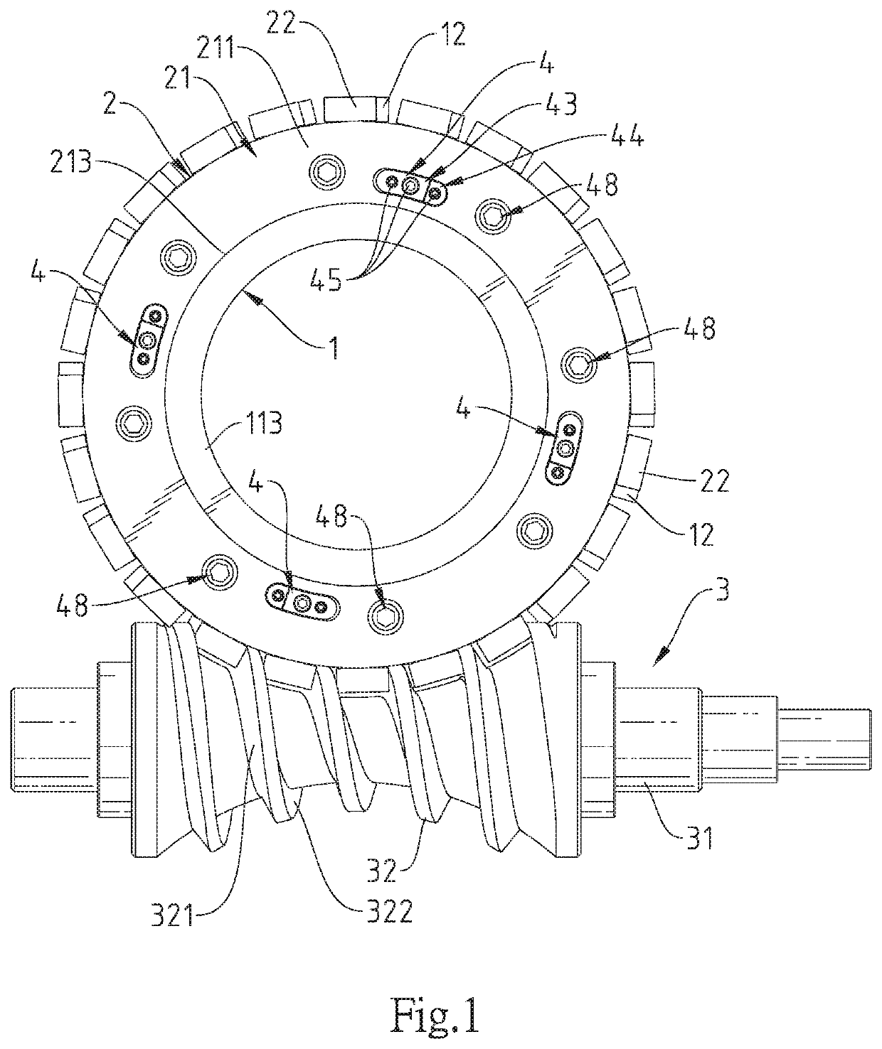
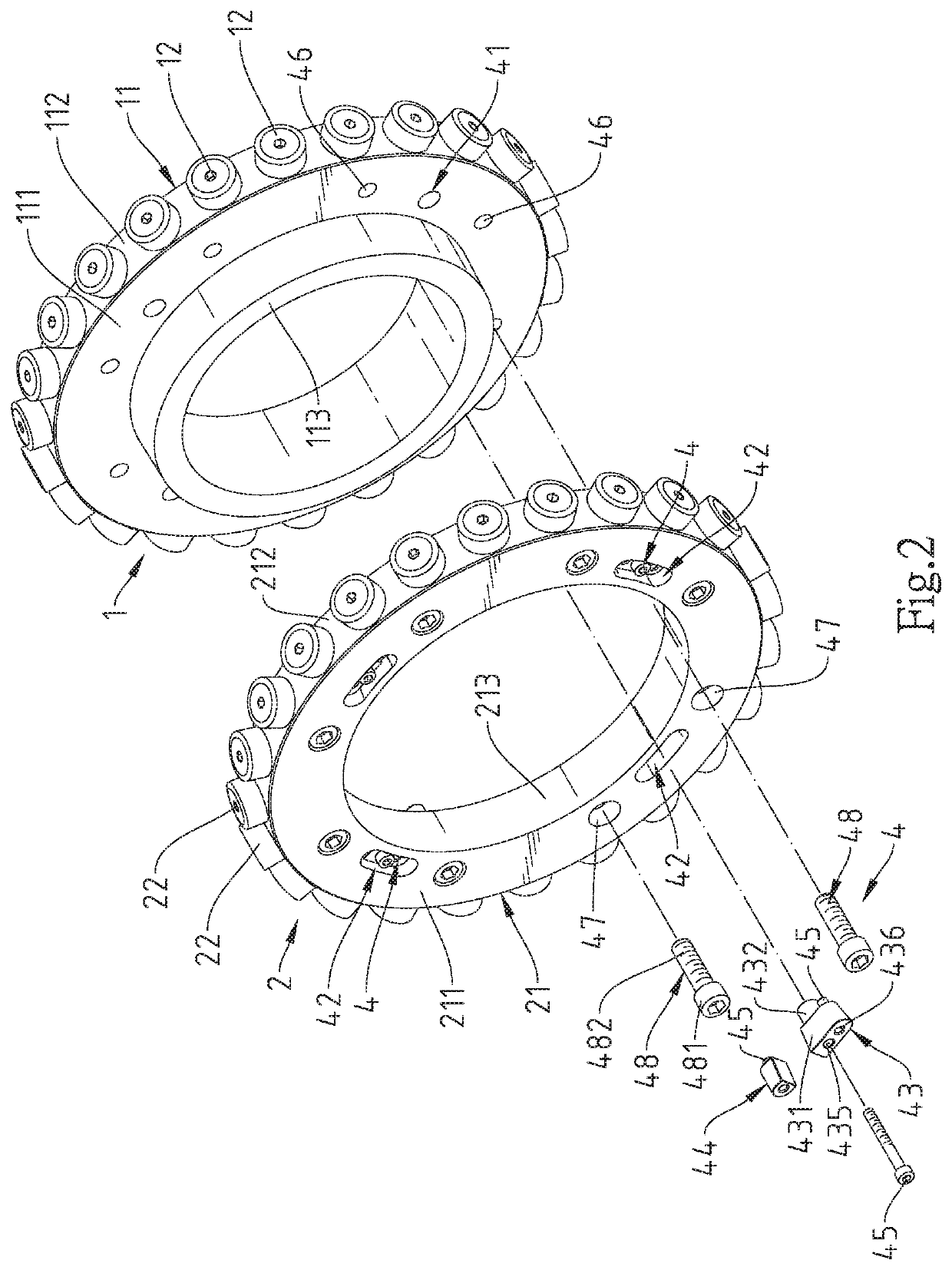
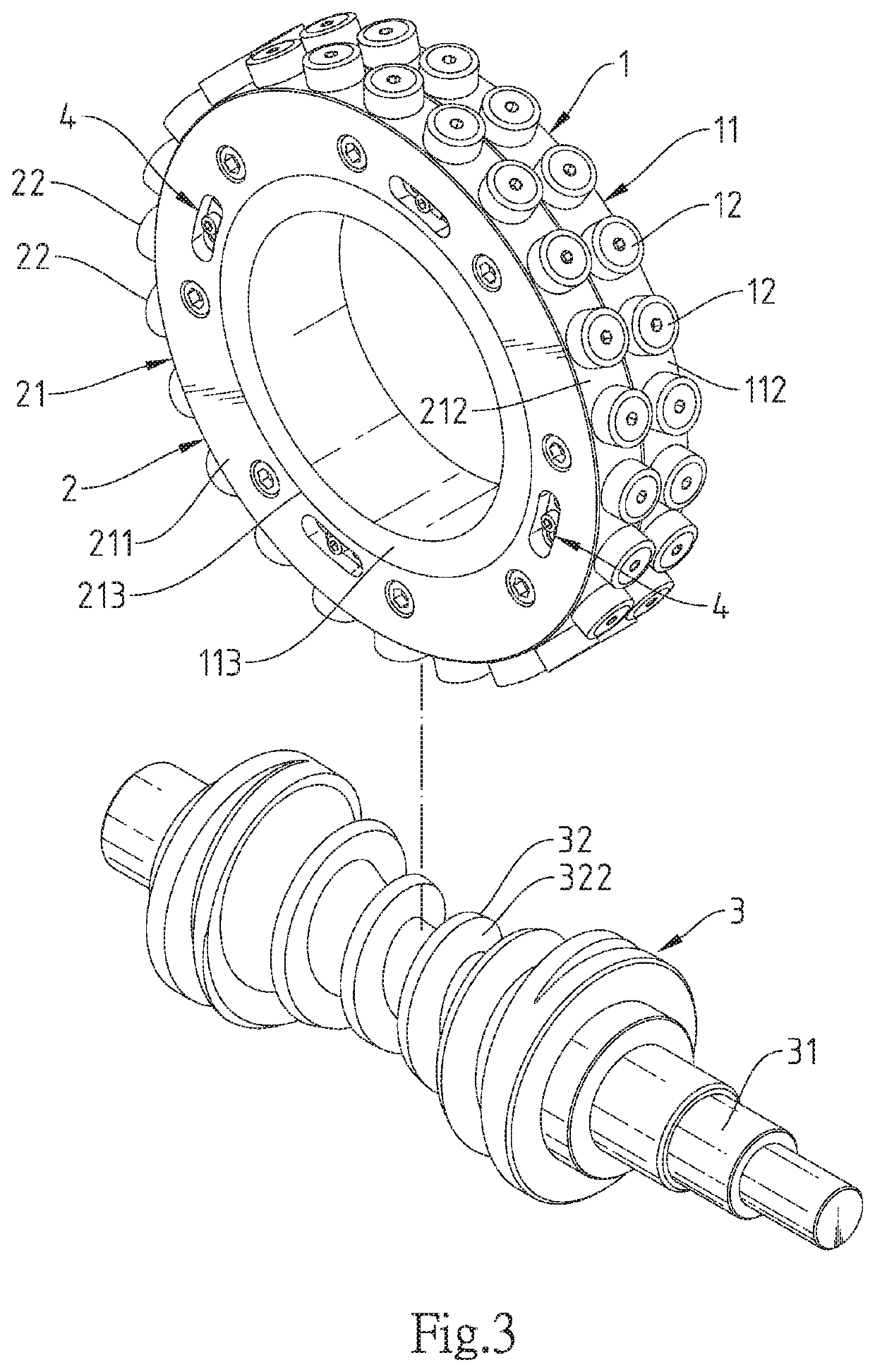
[0011]Referring to FIGS. 1-5, a double row roller cam transmission mechanism with backlash adjustment means in accordance with the present invention is shown. The double row roller cam transmission mechanism with backlash adjustment means comprises a first passive wheel 1, a second passive wheel 2, a transmission shaft 3 and an adjustment device set 4.

[0012]The first passive wheel 1 comprises a first rotating wheel 11 and a plurality of first rollers 12. The first rotating wheel 11 comprises a first wheel body 111, a first connection surface 112 formed of an outer peripheral surface of the first wheel body 111, and a shaft portion 113 perpendicularly extended from one lateral side of the first wheel body 111. The first rollers 12 are pivotally disposed around the first connection surface 112 of the first rotating wheel 11.

[0013]The second passive wheel 2 comprises a second rotating wheel 21 and a plurality of second rollers 22. The second rotating wheel 21 comprises a second wheel b...


PUM


Abstract

A double row roller cam transmission mechanism with backlash adjustment means is disclosed to include two passive wheels respectively provided with rollers, a transmission shaft with a spiral protrusion, and an adjustment device set operable to adjust the relative position between the two passive wheels so that the rollers of the two passive wheels can be respectively and positively abutted against the two opposite surfaces of the spiral protrusion of the transmission shaft to eliminate the backlash between the rollers and the spiral protrusion and to increase structural rigidity and transmission load

Description

BACKGROUND OF THE INVENTION1. Field of the Invention[0001]The present invention relates to cam transmission technology and more particularly, to a double row roller cam transmission mechanism with backlash adjustment means, which provides an adjustment device set that can be operated to adjust the relative position between two passive wheels so that the two passive wheels can be respectively and positively abutted against the two opposite surfaces of the spiral protrusion of the transmission shaft to eliminate the backlash between the two passive wheels and the spiral protrusion of the transmission shaft.2. Description of the Related Art[0002]When the cam transmission mechanism is operated at high speed, the inertia load is large, so it is easy to generate negative torque. If there is a backlash between the cam and the rollers, a knock will occur and vibration will be generated, reducing the transmission efficiency and accuracy and shortening the service life of the cam. Therefore, ...

Claims


Application Information

Patent Timeline
Patent Type & Authority Applications(United States)
IPC IPC(8): F16H55/24F16H1/16
CPCF16H1/166F16H55/24
Inventor CHIU, CHUI-TSAI
Owner CHIU CHUI TSAI
Why Eureka
Try Eureka