Rotary input robot for testing oscillating performance of overhead power transmission line

A technology of overhead transmission lines and robots, which is applied in vibration testing, testing of machines/structural components, manipulators, etc., can solve problems such as increasing complexity, and achieve the effects of convenient installation and layout, reducing complexity, and improving rigidity

Active Publication Date: 2015-04-01
CHINA ELECTRIC POWER RES INST +1
View PDF7 Cites 0 Cited by
  • Summary
  • Abstract
  • Description
  • Claims
  • Application Information

AI Technical Summary

Problems solved by technology

Since this scheme only uses one motor, the adjustment of the ratio of the major and minor axes of the elliptical trajectory and the inclination of the elliptical trajectory must be done manually or through other power devices, which increases the complexity of the scheme.

Method used


Image

  • Rotary input robot for testing oscillating performance of overhead power transmission line
  • Rotary input robot for testing oscillating performance of overhead power transmission line
  • Rotary input robot for testing oscillating performance of overhead power transmission line

Examples


Embodiment 1

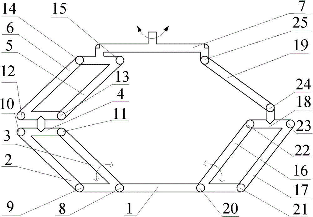
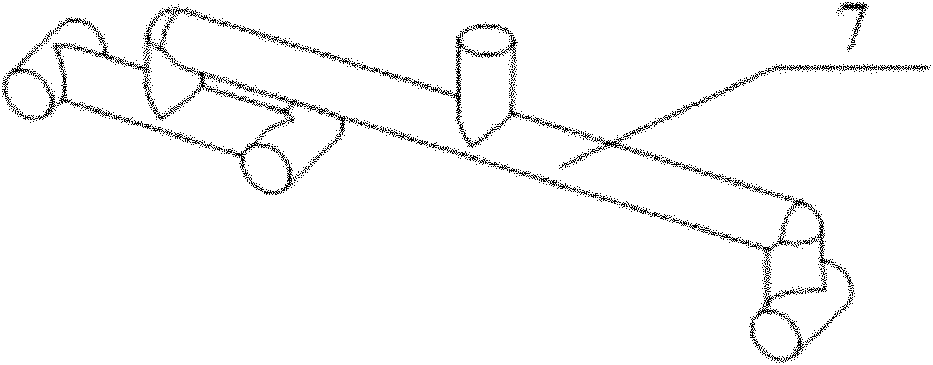
[0026] Such as figure 1 As shown, the robot includes a frame 1 and an end effector 7, one end of the end effector 7 is connected to the frame 1 through a first branch, and the other end of the end effector 7 is connected to the frame 1 through a second branch.

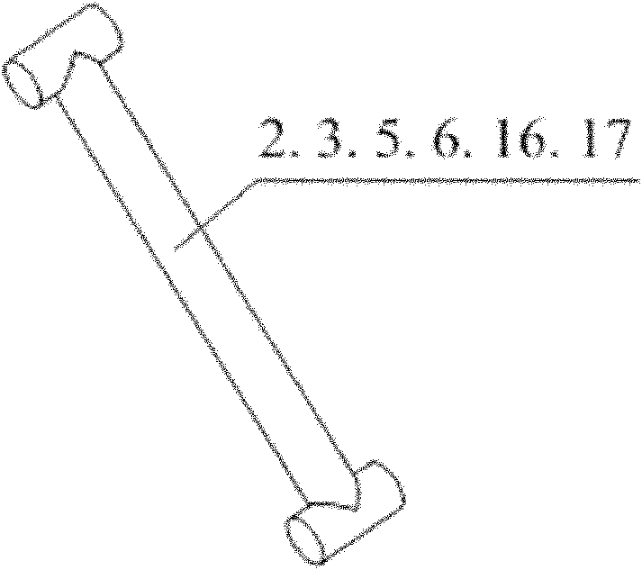
[0027] The first branch includes the first connecting piece 4, two first connecting rods 2, 3, two first connecting rods 5, 6, four first rotating pairs 8, 9, 10, 11 and four second rotating pairs Deputy 12, 13, 14, 15. The first rotating pair 8 of the first branch connects the frame 1 with the first connecting rod 3, the first connecting rod 3 is connected with the first connecting member 4 through the first rotating pair 11, and the first rotating pair 9 connects the first connecting rod. Frame bar 2, the first connecting frame bar 2 is connected with the connecting piece 4 through the rotating pair 10, that is, the frame 1, the first connecting frame bar 2, the first connecting frame bar 3 and the first connecting ...

Embodiment 2

[0032] The structure and working principle of the robot described in this example are basically the same as those in Embodiment 1, except that:

[0033] Such as Figure 6As shown, the second branch I of the robot in Embodiment 1 is replaced with the second branch II in this example, and the second branch II includes a third connecting frame rod 26, a moving pair 27, a third connecting rod 30 and two second connecting rods. Five rotation pairs 28, 29, the third connecting rod 30 is connected with the third connecting rod 26 through the moving pair 27, the third connecting rod 30 is connected with the end effector 7 through the fifth rotating pair 28, and the third connecting rod 26 is connected through The fifth revolving pair 29 is connected with the frame 1; the structure of the first branch of the robot is exactly the same as that of the first embodiment, and will not be repeated here. The axes of the four first rotating pairs 8, 9, 10, 11, the four second rotating pairs 12...


PUM


Abstract

The invention belongs to the field of a robot for testing an overhead power transmission line and particularly relates to a rotary input robot for testing the oscillating performance of the overhead power transmission line. The robot comprises a frame and a tail end actuator, wherein one side of the tail end actuator is connected with the frame through a first branch and the other side of the tail end actuator is connected with the frame through a second branch I or a second branch II. Due to the adoption of the robot, not only can the rigidity of the robot be improved, but also the load capacity of the robot can be improved. The robot is beneficial for bearing a large load in the process of testing the oscillating performance of the transmission line. Particularly, the robot consisting of a parallel four-bar mechanism has a more obvious effect. The robot carries out rotary input by rotating an auxiliary driving robot and is convenient to install and place a revolute pair, so that the inertia load of the robot is reduced and the robot is more convenient to install and place. The tail end actuator of the robot does not have the rotating motion function and can only move in a plane, so that the complexity of programming a robot control program can be reduced.

Description

technical field [0001] The invention belongs to the field of performance testing robots for overhead power transmission lines, in particular to a rotary input robot for testing galloping performance of overhead power transmission lines. Background technique [0002] When the wind in the horizontal direction blows to the transmission wire with a non-circular cross-section due to ice coating, a certain amount of aerodynamic force will be generated. Under certain conditions, the wire will be induced to generate low frequency (about 0.1-3Hz), large amplitude ( Self-excited vibration about 5 to 300 times the diameter of the wire). The damage caused by galloping is multifaceted. The light ones cause flashover and tripping, and the serious ones cause damage to hardware and insulators, broken bones and wires, loosening and falling off of tower bolts, and even down towers, resulting in major power grid accidents. [0003] In the case of galloping, the number of times the conductor c...

Claims


Application Information

Patent Timeline
Patent Type & Authority Patents(China)
IPC IPC(8): B25J9/08G01M7/02
Inventor 杨加伦朱宽军刘彬孙娜牛海军
Owner CHINA ELECTRIC POWER RES INST
Why Eureka
Try Eureka