Movable Connector

Active Publication Date: 2019-11-28
IRISO ELECTRONICS CO LTD
View PDF0 Cites 3 Cited by
  • Summary
  • Abstract
  • Description
  • Claims
  • Application Information

AI Technical Summary

Benefits of technology

[0012]According to this configuration, the first contact point is pressed against the connection object by utilizing a reaction force generated due to the second contact point being pressed by the contact reinforcing portion. Thus, the contact pressure of the first contact point against the connection object can be increased.
[0013]In the movable connector, the contact reinforcing portion may have a projection, and the manipulation housing may have a retaining groove that movably holds the projection via a gap provided between the retaining groove and the projection. The gap thereby enables the contact reinforcing portion to move relative to the manipulation housing.
[0014]According to this configuration, the contact reinforcing portion is not fixed to but is movable relative to the manipulation housing. As a result, even if the circuit-board connection terminal or the connection object comes deviatingly into contact with the contact

Problems solved by technology

In this case, a user tends to mistakingly think that the engagement is completed when the user feels the insertion force becomes high.
As a result, the user may stop inserting the connection object halfway, or performance in engagement operation may deteriorate.
However, decreasing the contact pressure may cause the contact

Method used


Image

  • Movable Connector
  • Movable Connector
  • Movable Connector

Examples


modification examples

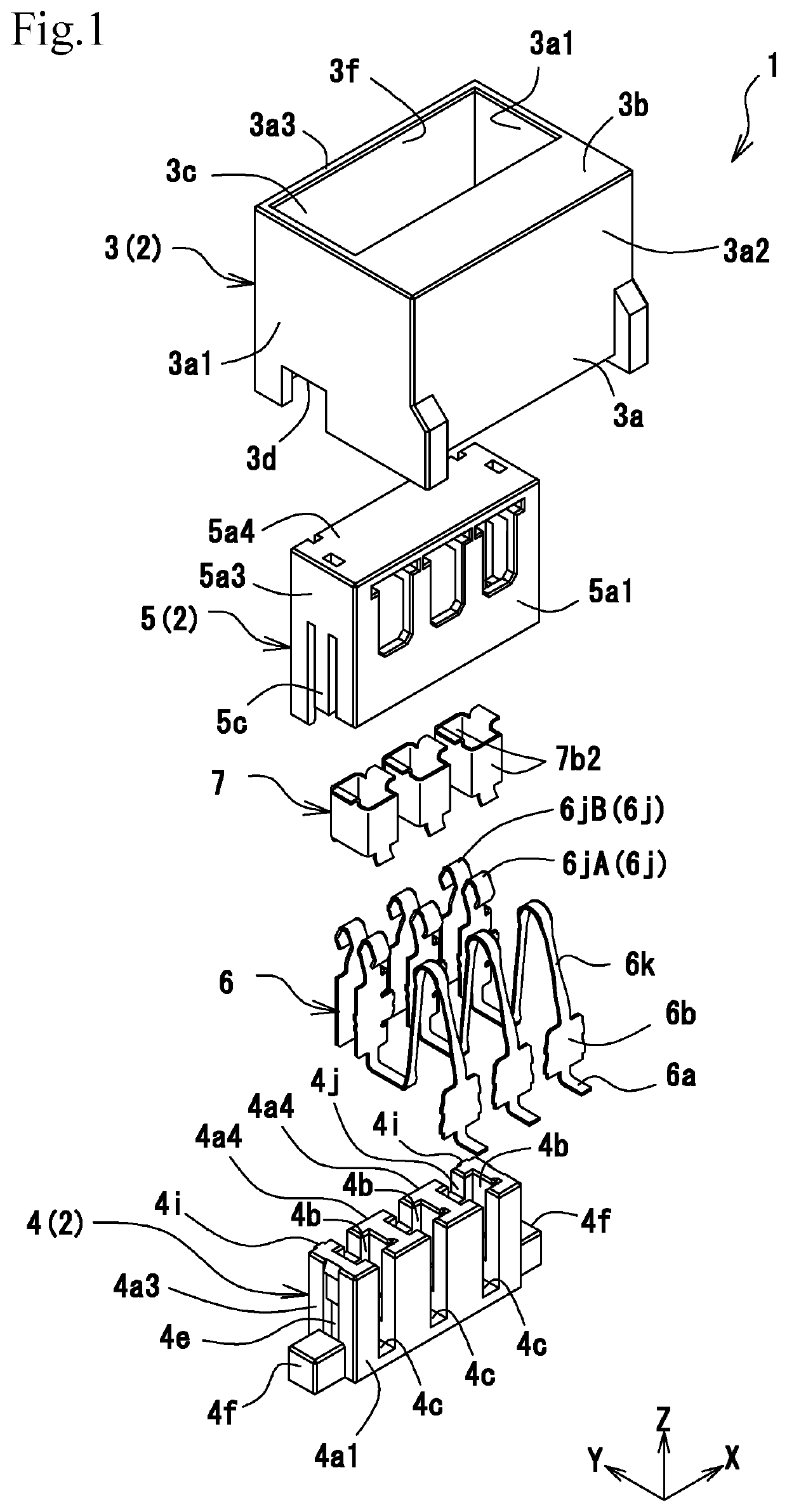
[0075]In the above embodiment, the “contact reinforcing portion” is exemplified as the contact reinforcing member 7 that is made of a metal piece. However, the contact reinforcing portion may be made of a resin (a resin molding). The “contact reinforcing portion” made of a resin may be formed as part of the manipulation housing 5 or may be molded into a body separate from the manipulation housing 5 and assembled into the manipulation housing 5 thereafter. The “contact reinforcing portion” formed in such a manner can reduce the production cost. On the other hand, in the case of the contact reinforcing member 7 being formed of a metal piece, a rigid metal piece may be used. This enables the contact portions 6j of the circuit-board connection terminal 6 to further increase the contact pressure. Here, in the case of the contact reinforcing member 7 being formed, for example, of a resin molding, when the contact portions 6j of the circuit-board connection terminal 6 are heated due to ele...


PUM


Abstract

There is provided a movable connector that facilitates easy engagement and improves stability in electrical connection. The movable connector includes a manipulation housing that is coupled to a movable housing by a pressing operation of the manipulation housing against the movable housing. The movable connector also includes a contact reinforcing member that moves together with the manipulation housing by the pressing operation. The contact reinforcing member comes into contact with a pair of contact portions of a circuit-board connection terminal and thereby presses the contact portions against a pin terminal.

Description

BACKGROUND OF THE INVENTION1. Field of the Invention[0001]The present invention relates to a connector having a floating function.2. Description of the Related Art[0002]An example of a known connector that electrically connects a connection object to the circuit of a circuit board is a bottom-entry type connector disclosed in Japanese Unexamined Patent Application Publication No. 2017-139101. The bottom-entry type connector or the connector 10 includes a fixed housing 11 to be mounted on a circuit board, a movable housing 12 to be accommodated in the fixed housing 11, and a terminal 13 having a movable member 13b that displaceably supports the movable housing 12 inside the fixed housing 11. In the movable housing 12, an insertion hole 12e is provided on a surface thereof that opposes the circuit board. In order to electrically connect a connection object (for example, a pin terminal or the like of an electrical element) to the connector 10, the connection object is inserted into the...

Claims


Application Information

Patent Timeline
IPC IPC(8): H01R13/631H01R12/70H01R12/91H01R13/187H01R13/405H01R13/502H01R12/57H01R12/71
CPCH01R12/91H01R13/193H01R12/716H01R13/6315H01R12/707H01R13/405H01R13/502H01R12/57H01R13/187
Inventor SUZUKI, HITOSHIKOBAYASHI, HIROAKIOGURA, YOSHIYUKISAITO, TOMOMITSUSHIMBA, DAICHI
Owner IRISO ELECTRONICS CO LTD
Why Eureka
Try Eureka