Supercharge Your Innovation With Domain-Expert AI Agents!

Cooling system for spatial light modulating devices

a technology of spatial light and cooling system, which is applied in the field of cooling system, can solve the problems of premature degradation of light valves and active heat transfer devices, not always performing the cooling system as expected, and achieve the effects of avoiding or at least minimizing overshoots and undershoots of temperature, prolonging the life or time, and improving the control of the temperature of the light valv

Active Publication Date: 2019-11-28
BARCO NV
View PDF4 Cites 11 Cited by
  • Summary
  • Abstract
  • Description
  • Claims
  • Application Information

AI Technical Summary

Benefits of technology

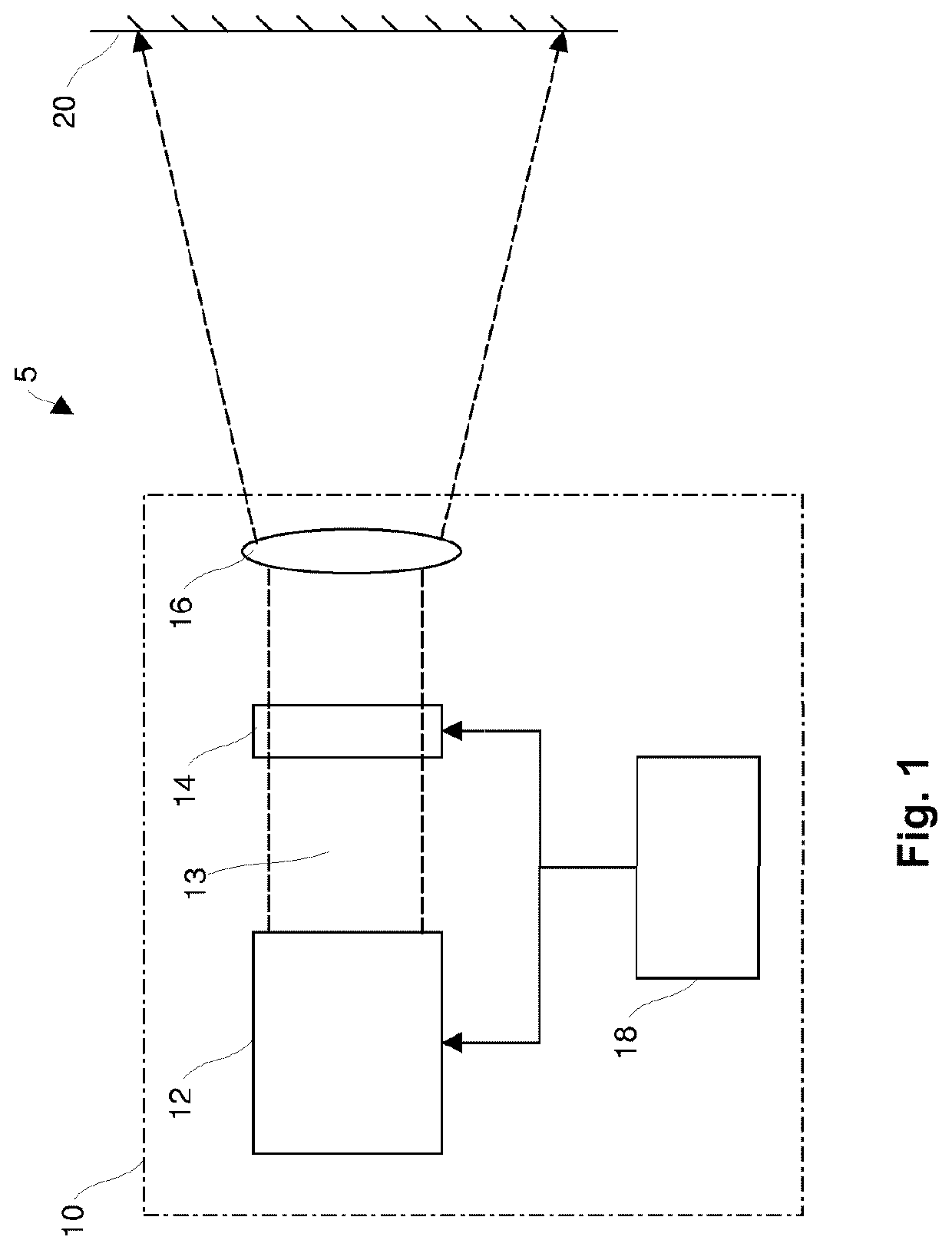
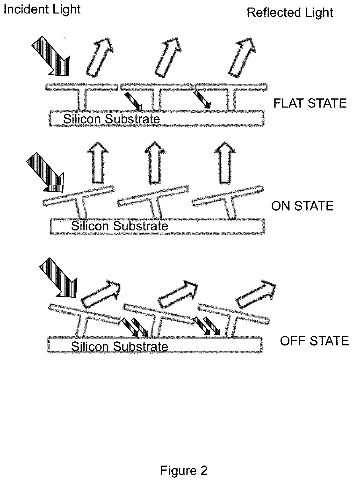
The invention is about controlling the temperature of a light valve or spatial light modulator in a projector by measuring and monitoring the radiative heat transfer between the light source and the light valve. By monitoring this heat transfer, the controller can anticipate temperature changes and avoid overshooting or undershooting. This allows for better control of the light valve's temperature and extends its lifespan. The amount of light reflected towards the projection optics or light dump can be measured to evaluate the configuration of the light valve and the rate at which heat transfer is done. This information can be used to modify the temperature control algorithm in real-time. The invention also includes a software sensor that analyzes the image data to determine the amount of light absorbed by the light valve and uses it to control the temperature. This eliminates the need for hardware and can be easily retrofitted to existing projectors.

Problems solved by technology

Unfortunately, with the ever-higher lumen output required, the cooling system proposed in U.S. Pat. No. 7,938,543 does not always perform as expected.
In particular, overshoots of the controlled temperatures can be observed which cause premature degradation of the light valves and of the active heat transfer devices.

Method used


Image

  • Cooling system for spatial light modulating devices
  • Cooling system for spatial light modulating devices
  • Cooling system for spatial light modulating devices

Examples


Embodiment Construction

[0112]The present invention will be described with respect to particular embodiments and with reference to certain drawings but the invention is not limited thereto but only by the claims. The drawings described are only schematic and are non-limiting. In the drawings, the size of some of the elements may be exaggerated and not drawn on scale for illustrative purposes. The dimensions and the relative dimensions do not correspond to actual reductions to practice of the invention.

[0113]Furthermore, the terms first, second, third and the like in the description and in the claims, are used for distinguishing between similar elements and not necessarily for describing a sequential or chronological order. It is to be understood that the terms so used are interchangeable under appropriate circumstances and that the embodiments of the invention described herein are capable of operation in other sequences than described or illustrated herein.

[0114]Moreover, the terms top, bottom, over, under...


PUM


Abstract

A cooling system for controlling the temperature of a light valve of a projection system, the light valve being illuminated by a light source, the cooling system including a first sensor for measuring a first temperature of a first part of the light valve, at least one active heating and / or cooling device to transfer heat between the light valve and a heat source and / or sink, a controller for controlling the temperature of the light valve with the at least one active heating and / or cooling device according to the first temperature with respect to a reference temperature. The cooling system further includes a sensor for determining the amount of light absorbed by the light valve, and where the controller is further configured to control the active heating and / or cooling device based on the amount of light absorbed by the light valve.

Description

TECHNICAL FIELD OF THE INVENTION[0001]The present invention relates to cooling systems for reflective spatial light modulating devices and optical systems comprising such a cooling system as well as to projectors and methods of operating projectors and a controller for controlling such methods, reflective spatial light modulating devices and optical systems and software for carrying out such methods when executed on a processing engine.BACKGROUND OF THE INVENTION[0002]Image modulating systems, also known as light engines, comprising a housing including spatial light modulating devices or light valves are well known. A spatial light modulating device may function either in a light transmissive mode, such as for LCD light modulators, or it may be a light reflective spatial light modulating device using DMD or LCD, e.g. LCOS, light modulators.[0003]Image modulating systems comprising reflective spatial light modulating devices based on mirrors may suffer less from heat generation than ...

Claims


Application Information

Patent Timeline
IPC IPC(8): H04N9/31H04N5/74G03B21/16G03B21/00G02B7/00
CPCH04N9/3144H04N9/3194G03B21/005G03B21/16G02B7/008H04N5/7441G02B5/003G02B26/0833
Inventor MALFAIT, BART CECILE PIETERCLEENEWERCK-DE-CRAYENCOUR, SIMON
Owner BARCO NV
Features
  • R&D
  • Intellectual Property
  • Life Sciences
  • Materials
  • Tech Scout
  • Unparalleled Data Quality
  • Higher Quality Content
  • 60% Fewer Hallucinations
Learn More