X-ray generator

a generator and x-ray technology, applied in the field of x-ray generators, can solve the problems of difficult to obtain x-ray images of high magnification, and achieve the effects of improving the monitoring precision of the other x-ray, prolonging the life of the x-ray monitor, and increasing the intensity

Inactive Publication Date: 2005-07-28
HAMAMATSU PHOTONICS KK
View PDF8 Cites 64 Cited by
  • Summary
  • Abstract
  • Description
  • Claims
  • Application Information

AI Technical Summary

Benefits of technology

[0010] The X-ray generator may further comprise a second exit window transmitting the other X-ray from the target. The second exit window is positioned on an X-ray path different from an X-ray path extending from the target to the first exit window. The X-ray monitor receives the other X-ray transmitted through the second exit window. The X-ray monitor receives the other X-ray with higher intensity in comparison to the case where the X-ray monitor receives the other X-ray transmitted through a wall of a housing or other obstruction, thereby improving the monitoring precision of the other X-ray.
[0011] The second exit window is preferably positioned so as to face a portion of a surface of the target on which the electron beam is incident. Since X-rays are generated strongly at the electron beam incidence portion and vicinity thereof of the target, the X-rays enter the X-ray monitor efficiently from the second exit window positioned so as to face the portion.
[0012] The second exit window may be a stem plate holding a terminal of the electron gun and through which the terminal extends. The X-ray generator in accordance with this invention may, for example, be manufactured using an X-ray tube that includes an electron gun and a target. In an X-ray tube, a stem plate, such as that described above, is often installed to electrically couple an electron gun to a driver for the electron gun. The stem plate may be formed of a material that sufficiently transmits X-rays such as insulating ceramic. Using the stem plate as the second exit window for transmitting the other X-ray makes it possible to manufacture the X-ray generator of this invention without greatly modifying an existing X-ray tube with the stem plate.
[0013] A shutter able to block the X-ray may be installed between the second exit window and the X-ray monitor. By blocking the X-ray using the shutter when it is not necessary to control the state of the X-ray, such as immediately after starting the generation of the X-ray, the X-ray exposure of the X-ray monitor can be prevented to extend the lifetime of the X-ray monitor.
[0014] The X-ray generator may further comprise a housing in which the electron gun, first exit window, target, and X-ray monitor are installed. In this case, the structure of the X-ray generator can be simplified and installation of the X-ray generator becomes easier.
[0015] The electron gun, the X-ray monitor and the portion of the surface of the target onto which the electron beam is incident may be housed in an enclosure capable of being maintained under vacuum. In this case, the control of the temperature, humidity, etc., of the X-ray monitor is facilitated. The X-ray monitoring precision can thus be improved further. The X-ray monitor may be installed in the enclosure so as to face the part of the surface of the target on which the electron beam is incident. Since the X-ray is generated strongly at the electron beam incidence portion and vicinity thereof of the target, the X-ray efficiently enters the X-ray monitor from the second exit window positioned so as to face the portion. The X-ray monitoring precision can thereby be improved further.

Problems solved by technology

S55-124997, though the variation of the X-ray dosage can be reduced, it is difficult to obtain X-ray images of high magnification.

Method used


Image

  • X-ray generator
  • X-ray generator
  • X-ray generator

Examples


first embodiment

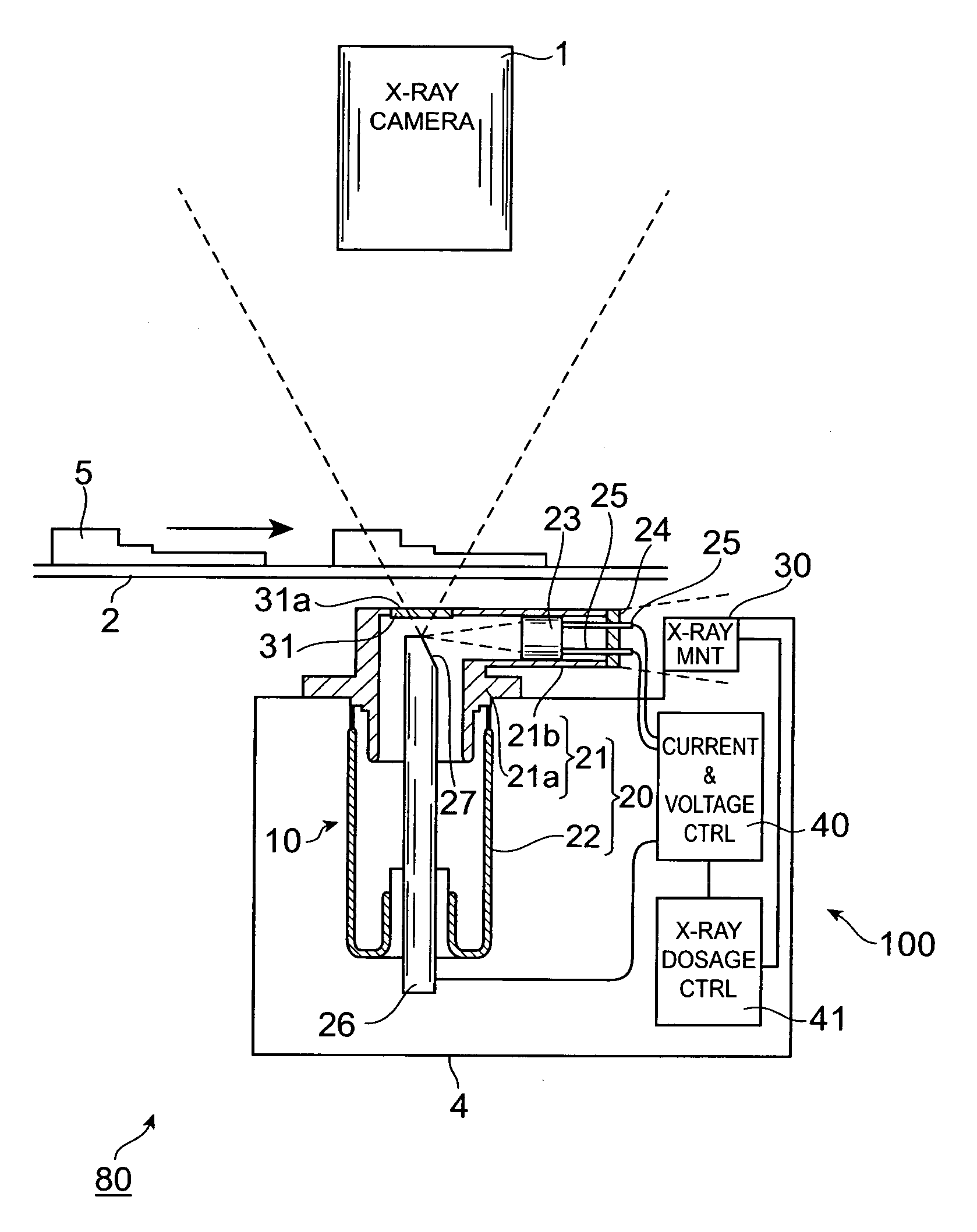
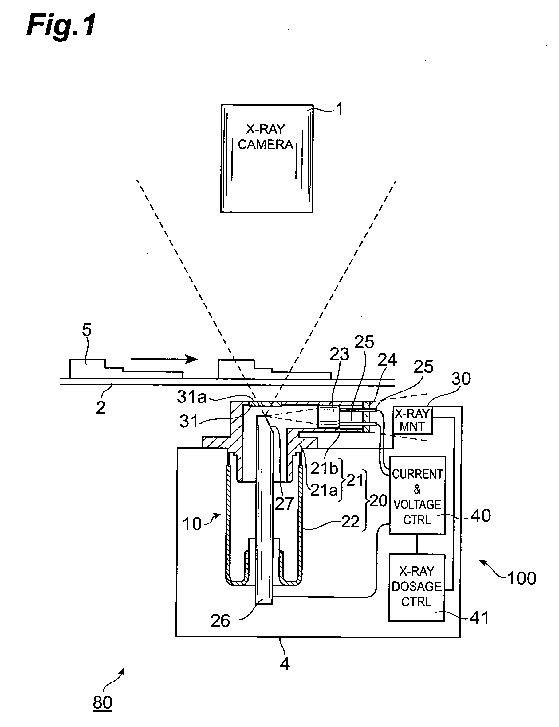
[0027]FIG. 1 is a schematic view showing a non-destructive inspection system having an X-ray generator of the first embodiment of the invention. This non-destructive inspection system 80 is for non-destructive inspection of an object 5 to be inspected. System 80 has a moving stage 2, a microfocusing type X-ray generator 100, and an X-ray camera 1. Moving stage 2 is able to be moved in horizontal directions, and a plurality of objects 5 to be inspected are placed on the top of moving stage 2. X-ray generator 100 is installed below moving stage 2 and irradiates the moving stage 2 with X-rays. X-ray camera 1 detects the X-rays transmitted through moving stage 2 and object 5 to acquire X-ray images.

[0028] X-ray generator 100 has, as principal components, an X-ray tube 10, an X-ray monitor 30 and a current and voltage controller 40. X-ray tube 10 emits X-rays generated from a reflection type target 27 upwardly. X-ray monitor 30 measures the dosage of the X-rays generated at X-ray tube 1...

second embodiment

[0044] An X-ray generator 200 of the second embodiment will now be described with reference to FIGS. 3 and 4. X-ray generator 200 differs from X-ray generator 100 of the first embodiment in having an X-ray tube 11 in place of X-ray tube 10. X-ray tube 11 has a second exit window 50 for transmitting X-rays from reflection type target 27 to the outside. Accordingly, X-ray monitor 30 does not oppose stem plate 24 but opposes second exit window 50.

[0045] Second exit window 50 is formed of Be or other substance with high X-ray transmittance and is fitted into a side wall of trunk part 21a of vacuum enclosure 20. The position of second exit window 50 is not restricted in particular; however, it is preferably installed at a position that faces the portion of the surface of target 27 on which the electron beam is incident so that X-rays with adequate intensity emerges through it.

[0046] A preferable arrangement of second exit window 50 and X-ray monitor 30 is shown specifically in FIG. 4. ...

third embodiment

[0048] An X-ray generator 300 of the third embodiment will now be described with reference to FIG. 5. X-ray generator 300 differs from the second embodiment in having a transmission type X-ray tube 12 in place of reflection type X-ray tube 11. X-ray tube 12 has, in place of reflection type target 27 and first exit window 31 in X-ray tube 11, a transmission type target 60 which is fitted into the upper wall of trunk part 21a in substantially horizontal arrangement. Transmission type target 60 acts as both target 27 and first exit window 31 in the second embodiment. The upper surface of target 60 is an X-ray exit surface 60a and the lower surface is an electron beam incidence surface 60b.

[0049] Correspondingly, electron gun 23 is positioned below target 60 in the interior of trunk part 21a and is installed so as to emit an electron beam upward towards electron beam incidence surface 60b. Second exit window 50 is installed in the side wall of trunk part 21a so as to face electron beam...


PUM

PropertyMeasurementUnit
angleaaaaaaaaaa
densityaaaaaaaaaa
temperatureaaaaaaaaaa

Abstract

An X-ray generator of this invention has an X-ray monitor that monitors a state of an X-ray emitted from a target. Hence the state of the X-ray can be monitored in real time to maintain the X-ray in a constant state. The X-ray monitor is positioned off the path on which an X-ray transmitted from a first exit window travels. Hence, when the X-ray is emitted from the first exit window to an object to be inspected, the X-ray monitor does not obstruct the approaching of the object to the first exit window. This makes it possible to acquire X-ray images of high magnification.

Description

TECHNICAL FIELD [0001] This invention relates to an X-ray generator for irradiating a target with an electron beam to generate X-rays. BACKGROUND ART [0002] The inspection device which irradiates an object to be inspected with X-rays and taking an image of the X-rays transmitted through the object has been known previously. An X-ray generator can be used as an X-ray source for such an inspection device. The X-ray generator generates X-rays by irradiating a target with an electron beam. The X-ray dosage varies according to the acceleration voltage applied to the electron beam, the current value of the electron beam or the like, as well as according to the damage of the target, the thermal deformation of the target supporting member, etc. [0003] In response to the variation of the dosage of the X-rays applied to an object to be inspected varies, the image of the X-rays transmitted through the object changes. In such a case, it cannot be distinguished whether this change is due to char...

Claims


Application Information

Patent Timeline
Patent Type & Authority Applications(United States)
IPC IPC(8): G21K5/00G21K5/02H01J35/18H05G1/26G01N23/04H05G1/30H05G1/36
CPCG01N23/04H05G1/36H05G1/30
Inventor INAZURU, TUTOMU
Owner HAMAMATSU PHOTONICS KK
Why Eureka
Try Eureka