Vehicular power supply system

a power supply system and vehicle technology, applied in emergency power supply arrangements, battery/fuel cell control arrangements, hybrid vehicles, etc., can solve the problems of limiting the blinking cycle, difficult to reduce the number of components, and difficult to manage the remaining amount of power stored by the power source, so as to prevent the interruption of power supply and avoid wasteful discharge of power from the in-vehicle battery or the like

Inactive Publication Date: 2019-12-05
YAZAKI CORP
View PDF0 Cites 8 Cited by
  • Summary
  • Abstract
  • Description
  • Claims
  • Application Information

AI Technical Summary

Benefits of technology

[0023]According to the vehicular power supply system configured as (3), the priorities of the loads to which the power should be supplied can be appropriately corrected according to the situation where the vehicle is installed, such as the traveling state of the vehicle, the state of the occupant, the environment outside the vehicle or the like, so that it is possible to prevent interruption of power supply to the load for which driving should be continued in each situation.
[0024]According to the vehicular power supply system of the present invention, wasteful discharge of power from an in-vehicle battery or the like can be avoided, and appropriate balance between the power demand and power supply capacity can be maintained even if the load increases.

Problems solved by technology

However, when a lamp control circuit such as a mechanical relay is used, there is a limit in the blinking cycle, and it is also difficult to reduce the number of components.
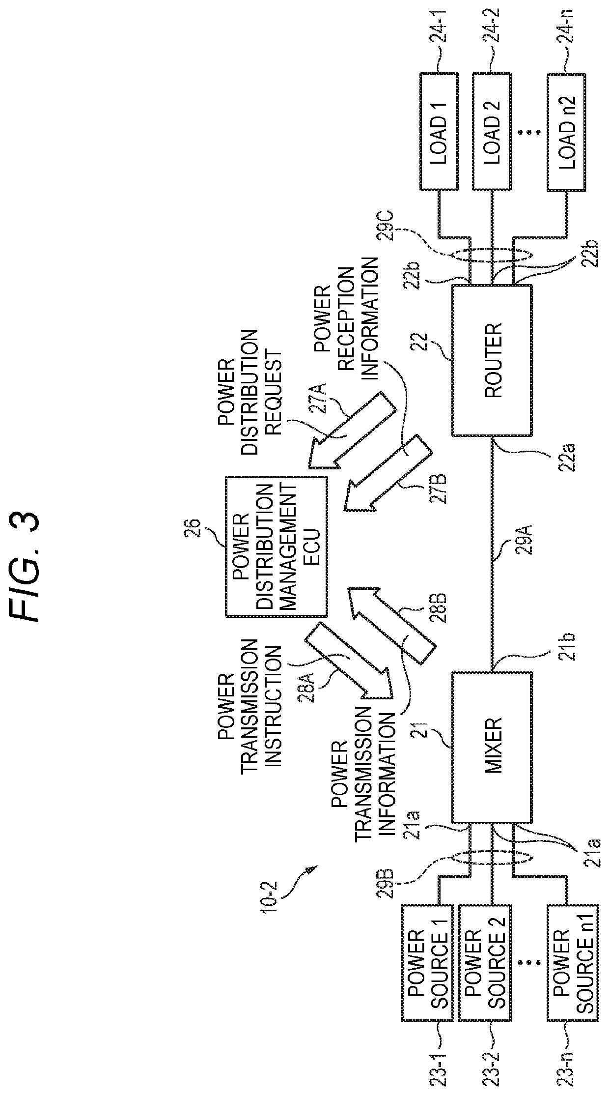
In addition, even when all the loads 24-1 to 24-n do not consume the power, since the power from the power sources 23-1 to 23-n is consumed, it may be difficult to manage the remaining amount of the power stored by the power sources 23-1to 23-n, and there may be a problem of dark current.

Method used


Image

  • Vehicular power supply system
  • Vehicular power supply system
  • Vehicular power supply system

Examples


Embodiment Construction

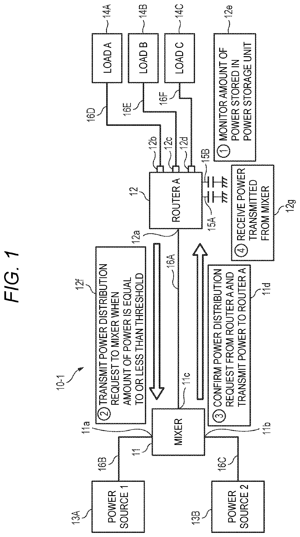
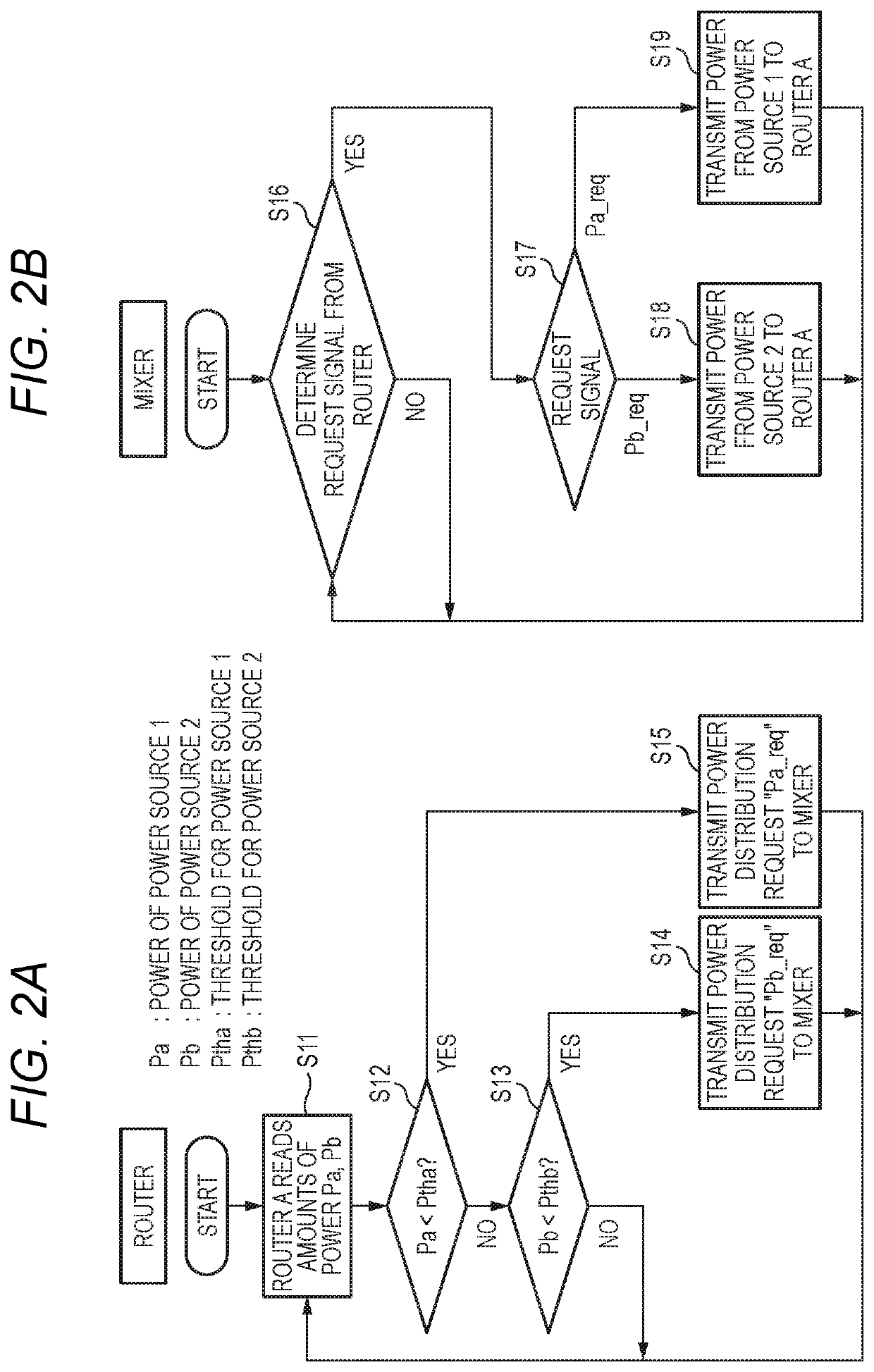
of a power supply system according to the embodiment of the present invention.

[0047]FIG. 23A is a block diagram showing Configuration Example 11 of a power supply system according to the embodiment of the present invention, and FIG. 23B and FIG. 23C are time charts showing variation examples of power packets output to a transmission path of each part in different operations,

[0048]FIG. 24 is a block diagram showing Configuration Example 12 of a power supply system according to the embodiment of the present invention.

[0049]FIG. 25 is a block diagram showing Configuration Example 13 of a power supply system according to the embodiment of the present invention.

[0050]FIG. 26 is a block diagram showing Configuration Example 14 of a power supply system according to the embodiment of the present invention.

[0051]FIG. 27 is a block diagram showing a configuration example of a common lamp control circuit.

[0052]FIG. 28 is a block diagram showing a configuration example of a lamp control circuit...


PUM


Abstract

A vehicular power supply system is provided with: a power supply control unit for supplying a power packet from a power packet mixer to power packet routers in response to a power distribution request from the power packet routers; and an allocation unit for allocating priorities to a plurality of loads. The power supply control unit restricts power supply to a load having a low priority when the demand-supply relationship of power satisfies a predetermined condition.

Description

CROSS REFERENCE TO RELATED APPLICATIONS[0001]This application is a continuation of PCT application No. PCT / JP2018 / 011545, which was filed on Mar. 22, 2018, based on Japanese Patent Application No. 2017-056002 filed on Mar. 22, 2017, Japanese Patent Application No. 2017-231241 filed on Nov. 30, 2017, Japanese Patent Application No. 2017-231242 field on Nov. 30, 2017, Japanese Patent Application No. 2017-231243 filed on Nov. 30, 2017, Japanese Patent Application No. 2017-231244 filed on Nov. 30, 2017, Japanese Patent Application No. 2017-231245 filed on Nov. 30, 2017, Japanese Patent Application No. 2017-231246 filed on Nov. 30, 2017, Japanese Patent Application No. 2017-231247 filed on Nov. 30, 2017, Japanese Patent Application No. 2017-231248 filed on Nov. 30, 2017, Japanese Patent Application No. 2017-231249 filed on Nov. 30, 2017, Japanese Patent Application No. 2017-231250 filed on Nov. 30, 2017, Japanese Patent Application No. 2017-231252 filed on Nov. 30, 2017, Japanese Patent ...

Claims


Application Information

Patent Timeline
Patent Type & Authority Applications(United States)
IPC IPC(8): B60L58/12H02J9/06H02J9/00B60L5/00B60W20/13
CPCB60L58/12B60W20/13H02J9/061H02J9/002B60L5/00B60L1/00B60R16/03B60W10/06B60W10/08B60W10/26B60W2710/242B60W20/12H02J1/14H02J1/084H02J1/106H02J2310/40H02J2310/60H02J2310/62Y02T10/40Y02T10/62Y02T10/70Y02T10/92Y02T90/16
Inventor KANAMORI, KATSUMIURUSHIBATA, TAKUROTANIGAWA, JUNYAUSHITANI, KOICHIMAEZAKI, DAISUKE
Owner YAZAKI CORP
Why Eureka
Try Eureka