
Electric brake system and control method thereof

Active Publication Date: 2019-12-05
HL MANDO CORP
View PDF0 Cites 4 Cited by
  • Summary
  • Abstract
  • Description
  • Claims
  • Application Information

AI Technical Summary

Benefits of technology

The present patent is about an electronic brake system that can still generate brake force when the pedal simulator valve fails. The system includes a master cylinder, a pedal displacement sensor, a simulation apparatus, a hydraulic pressure supply unit, a hydraulic circuit, a cut valve, a controller, and a simulator pressure sensor. The controller can block the cut valve or enter a fallback mode when a failure occurs in the system. The system can also store the oil discharged from the master cylinder and adjust the hydraulic pressure transferred to the simulation chamber. The technical effect of the patent is to provide a reliable and safe electronic brake system that can still control braking even in the event of failure.

Problems solved by technology

However, when the pedal simulator valve fails during the pedal simulator operation, the pedal feeling could not be provided to the driver, and resulting in a problem that the braking force of the vehicle could not be generated.
Further, the controller may block the cut valve when a failure in the electronic brake system is a failure of the simulator valve.
Further, the controller may enter a fallback mode when it is determined that a failure other than the simulator valve has occurred in the electronic brake system.
Further, the controller may determine that the simulator valve fails when the hydraulic pressure in the simulator chamber is greater than first predetermined hydraulic pressure.
Further, the controller may periodically open the cut valve after shutting off the cut valve when the simulation apparatus fails.
Further, the method may further include shutting off the cut valve when a failure in the electronic brake system is a failure of the simulator valve; and entering a fallback mode when it is determined that a failure other than the simulator valve has occurred in the electronic brake system.

Method used


Image

  • Electric brake system and control method thereof
  • Electric brake system and control method thereof
  • Electric brake system and control method thereof

Examples


Embodiment Construction

[0034]Reference will now be made in detail to the embodiments of the present disclosure, examples of which are illustrated in the accompanying drawings. The embodiments to be described below are provided to fully convey the spirit of the present disclosure to a person skilled in the art. The present disclosure is not limited to the embodiments disclosed herein and may be implemented in other forms. In the drawings, some portions not related to the description will be omitted and will not be shown in order to clearly describe the present disclosure, and also the size of the component may be exaggerated or reduced for convenience and clarity of description.

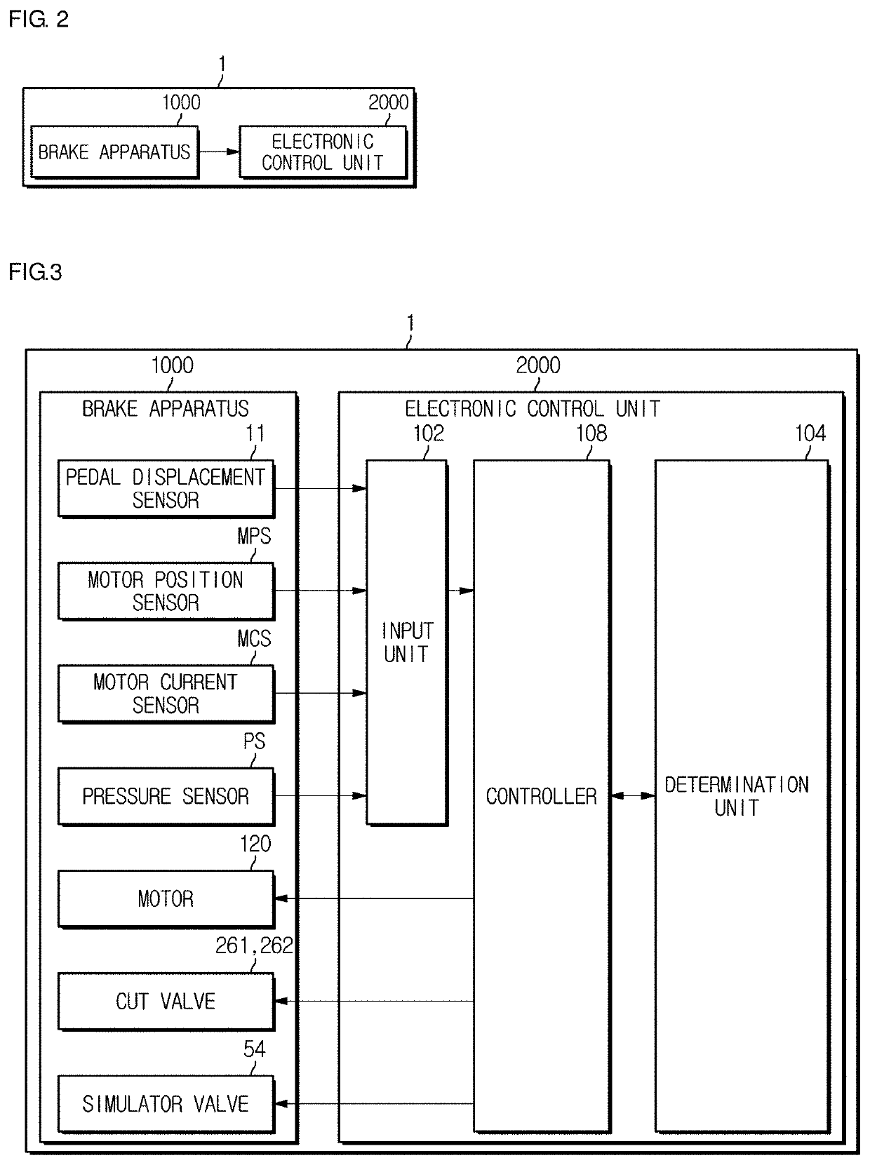
[0035]FIG. 1 is a circuit diagram illustrating an electronic brake system according to an embodiment of the present disclosure. Referring to FIG. 1, the electronic brake system 1 according to the embodiment may include a reservoir 30 for storing oil by being coupled to an upper portion of a master cylinder 20 a caliper 40 including ...


PUM


Abstract

Disclosed herein is an electronic brake system and a method for controlling the same are disclosed. The electronic brake system includes a master cylinder for discharging oil according to displacement of a brake pedal, a pedal displacement sensor sensing brake pedal displacement, a simulation apparatus providing pedal pressure responsive to the sensed pedal displacement, a hydraulic pressure supply unit for generating hydraulic pressure using a motor that operates based on the sensed pedal displacement, a hydraulic circuit for supplying the hydraulic pressure generated from the hydraulic pressure supply unit to the caliper, a cut valve positioned between the master cylinder and the hydraulic circuit for transmitting or blocking the hydraulic pressure discharged from the master cylinder, and a controller for blocking at least one of the cut valve and braking control with a target pressure according to a pressure in the simulation apparatus when the simulation apparatus fails.

Description

CROSS-REFERENCE TO RELATED APPLICATION[0001]This application is based on and claims priority under 35 U.S.C. § 119 to Korean Patent Application No. 10-2018-0061702, filed on May 30, 2018 in the Korean Intellectual Property Office, the disclosure of which is incorporated by reference in its entirety.BACKGROUND1. Field[0002]Embodiments of the present disclosure relate to an electronic brake system, and more particularly to an electronic brake system and method for controlling thereof when a pedal simulator in the electronic brake system fails.2. Description of the Related Art[0003]In general, a vehicle is essentially equipped with a brake system for braking, and in recent years, various types of brake systems have been proposed to obtain a more powerful and stable braking force.[0004]Examples of brake systems include anti-lock brake systems (ABSs) to prevent wheels from sliding during braking, brake traction control systems (BTCSs) to prevent driving wheels from sliding when a vehicle...

Claims


Application Information

Patent Timeline
IPC IPC(8): B60T8/94B60T7/04B60T8/40
CPCB60T8/4086B60T2270/404B60T7/042B60T8/94B60T2270/82B60T13/745B60T13/662B60T2270/402B60T2220/04B60T8/4081B60T17/22B60Y2400/81
Inventor KIM, SANGHOON
Owner HL MANDO CORP
Features
  • Generate Ideas
  • Intellectual Property
  • Life Sciences
  • Materials
  • Tech Scout
  • Unparalleled Data Quality
  • Higher Quality Content
  • 60% Fewer Hallucinations
Learn More