
Variable torque differential

a torque differential and variable technology, applied in the field ofdifferential, can solve the problems of disadvantageous equal distribution of torque to the wheels, spin of the inner wheels, and understeering phenomena or oversteering phenomena, and achieve the effects of reliable and robust manner, efficient transfer, and reliable suppor

Inactive Publication Date: 2019-12-05
KONTOPOULOS FLORENTINA
View PDF7 Cites 0 Cited by
  • Summary
  • Abstract
  • Description
  • Claims
  • Application Information

AI Technical Summary

Benefits of technology

The patent describes a differential that allows for individual control of torque transfer to different drive wheels. This results in safer and faster driving, as well as better parking and reduced tire wear. The differential also allows for torque distribution between the front and rear wheels in an AWD vehicle. Overall, the invention improves the performance and efficiency of vehicles.

Problems solved by technology

As an open differential equally divides the torque to the wheels, there is a chance that the inner wheels spin or that understeering phenomena or oversteering phenomena occur, especially when the vehicle accelerates while turning.
Furthermore, when a wheel faces a low friction surface (e.g. a muddy or an icy road), the equal distribution of the torque to the wheels is disadvantageous, as the torque transferred to the wheel on the low friction surface is the same as the one transferred to the wheel on the higher friction surface.

Method used


Image

  • Variable torque differential
  • Variable torque differential
  • Variable torque differential

Examples


Embodiment Construction

[0033]In the following, the present invention will be described with reference to the figures. Therein, similar elements are provided with same reference numbers. It shows:

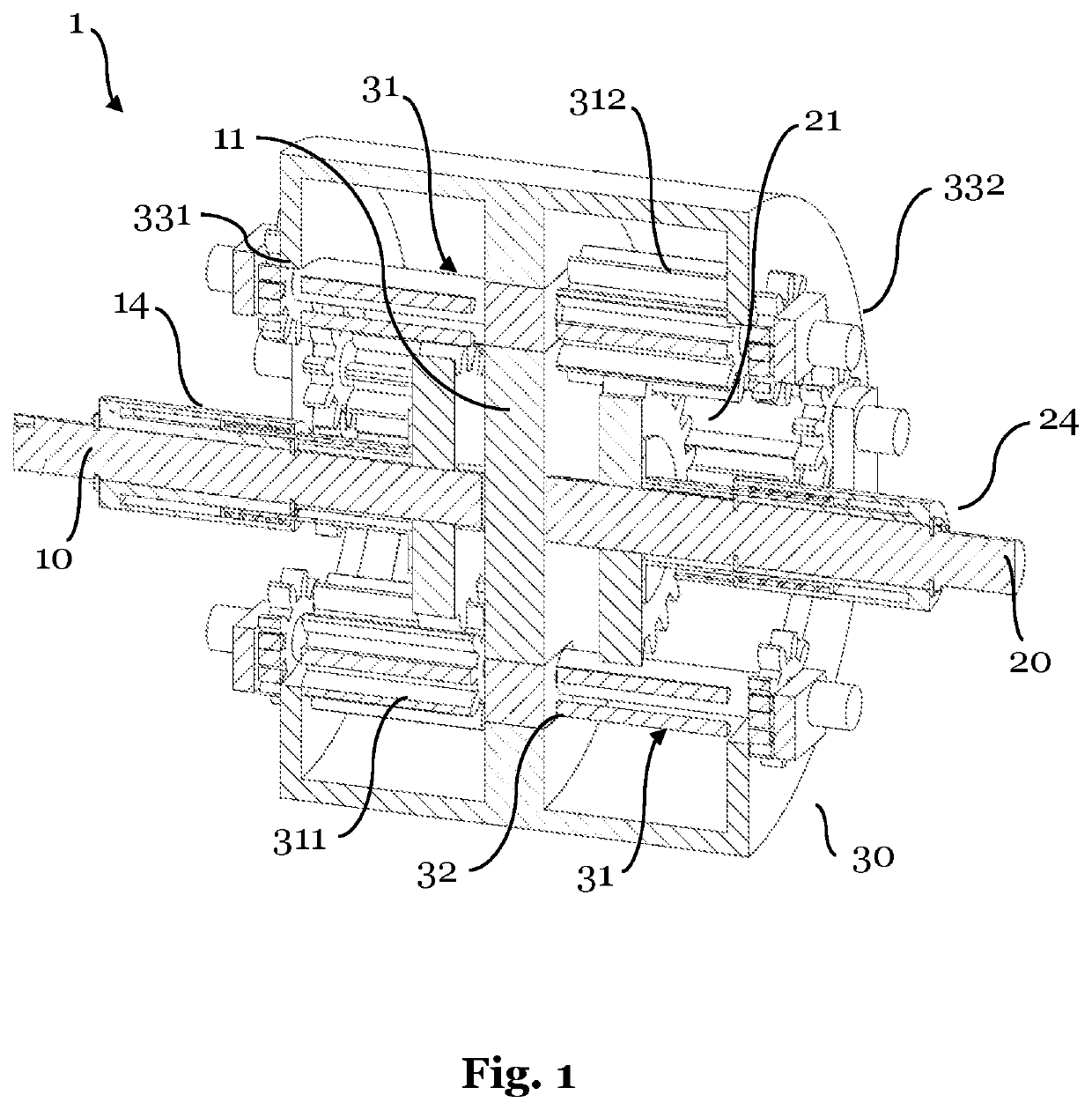
[0034]FIG. 1 a sectional view of a differential according to an embodiment of the invention;

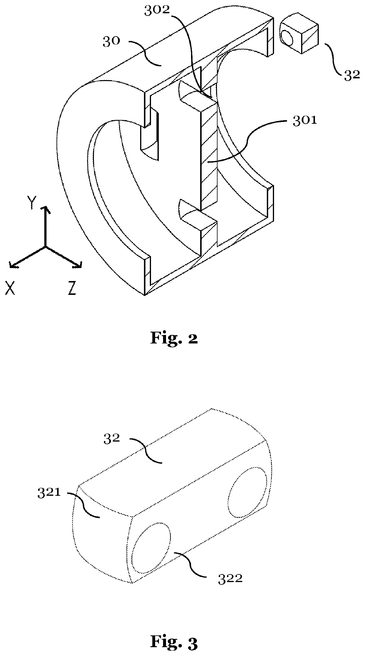
[0035]FIG. 2 a sectional view of individual parts of a differential according to the embodiment illustrated in FIG. 1;

[0036]FIG. 3 a connection part of a differential according to the embodiment illustrated in FIG. 1;

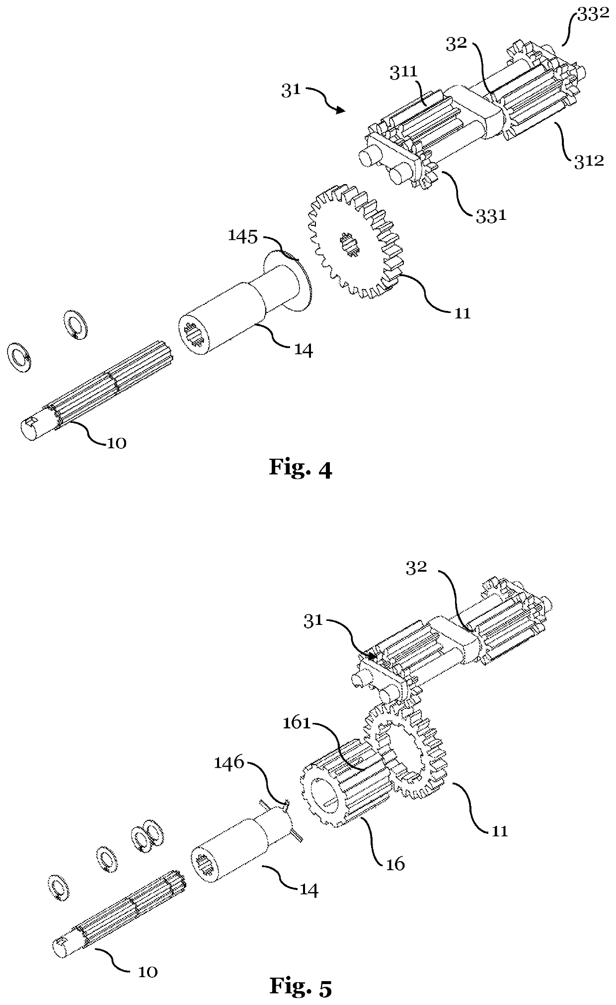
[0037]FIG. 4 individual parts of a differential according to the embodiment illustrated in FIG. 1;

[0038]FIG. 5 individual parts of a differential according to a further embodiment of the invention;

[0039]FIG. 6 a splined rail of a differential according to the embodiment illustrated in FIG. 5;

[0040]FIG. 7 a cross-sectional view of a differential according to a further embodiment of the invention;

[0041]FIG. 8 individual parts of a differential according to the embodiment illustrated in FIG. 7;

[0042]FIG. 9 individ...


PUM


Abstract

The present invention relates to a differential, and in particular to an automotive differential, for transferring a rotational force from an input member, for example connected to an automotive engine, to a first and a second output member, for example half-shafts of a drive axle of a vehicle. The differential thereby comprises a first gear connected to the first output member, a second gear connected to the second output member, and a third gear engaging both the first and second gear.

Description

1. TECHNICAL FIELD[0001]The present invention relates to a differential, in particular an automotive differential, a method for operating such a differential, and a vehicle comprising such a differential.2. TECHNICAL BACKGROUND[0002]When a wheeled vehicle, such as an automobile, turns, an outer wheel (i.e. a wheel travelling around the outside of the turning curve) typically rotates with greater speed compared to an inner wheel, as the outer wheels have to roll further than the inner wheels. For this purpose, a differential is typically applied which allows for the outer drive wheel to rotate faster than the inner drive wheel during a turn.[0003]The basic differential is the so-called open differential, by which the torque from an engine is equally divided to each wheel. The rotational speed may differ for each wheel, wherein the average of the rotational speed of the driving wheels equals the input rotational speed provided by the engine. An increase of speed of one (outer) drive w...

Claims


Application Information

Patent Timeline
Patent Type & Authority Applications(United States)
IPC IPC(8): F16H48/36F16H48/11
CPCF16H48/11F16H48/36
Inventor KONTOPOULOS, KONSTANTINOS
Owner KONTOPOULOS FLORENTINA
Learn More