Cooling device with evenly distributed and directed cooling effect for high heat flux and deaeration functionality

a cooling device and heat flux technology, applied in the direction of electrochemical generators, lighting and heating apparatuses, laminated elements, etc., can solve the problem of significant heat generation, and achieve good thermal properties

Active Publication Date: 2019-12-05
SAAB AB
View PDF0 Cites 7 Cited by
  • Summary
  • Abstract
  • Description
  • Claims
  • Application Information

AI Technical Summary

Benefits of technology

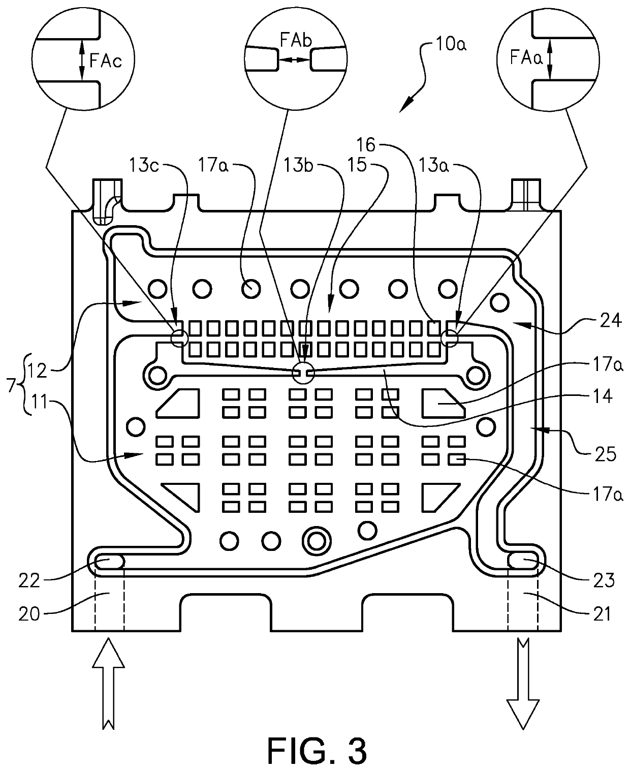
[0047]Yet an exemplary advantageous functionality provided by the present invention is that the cooling structure additionally provides a buffering effect. The surface enlarging elements, especially if they are solid, thus if the surface enlarging elements are formed of heat conductive material completely through respective element, increases the total mass of heat conductive material at the position of the cooling structure. This has the effect that even if an air pocket is formed at the cooling structure, whereby the

Problems solved by technology

During operation of high power electrical components, such as e.g. circuit

Method used


Image

  • Cooling device with evenly distributed and directed cooling effect for high heat flux and deaeration functionality
  • Cooling device with evenly distributed and directed cooling effect for high heat flux and deaeration functionality
  • Cooling device with evenly distributed and directed cooling effect for high heat flux and deaeration functionality

Examples


Embodiment Construction

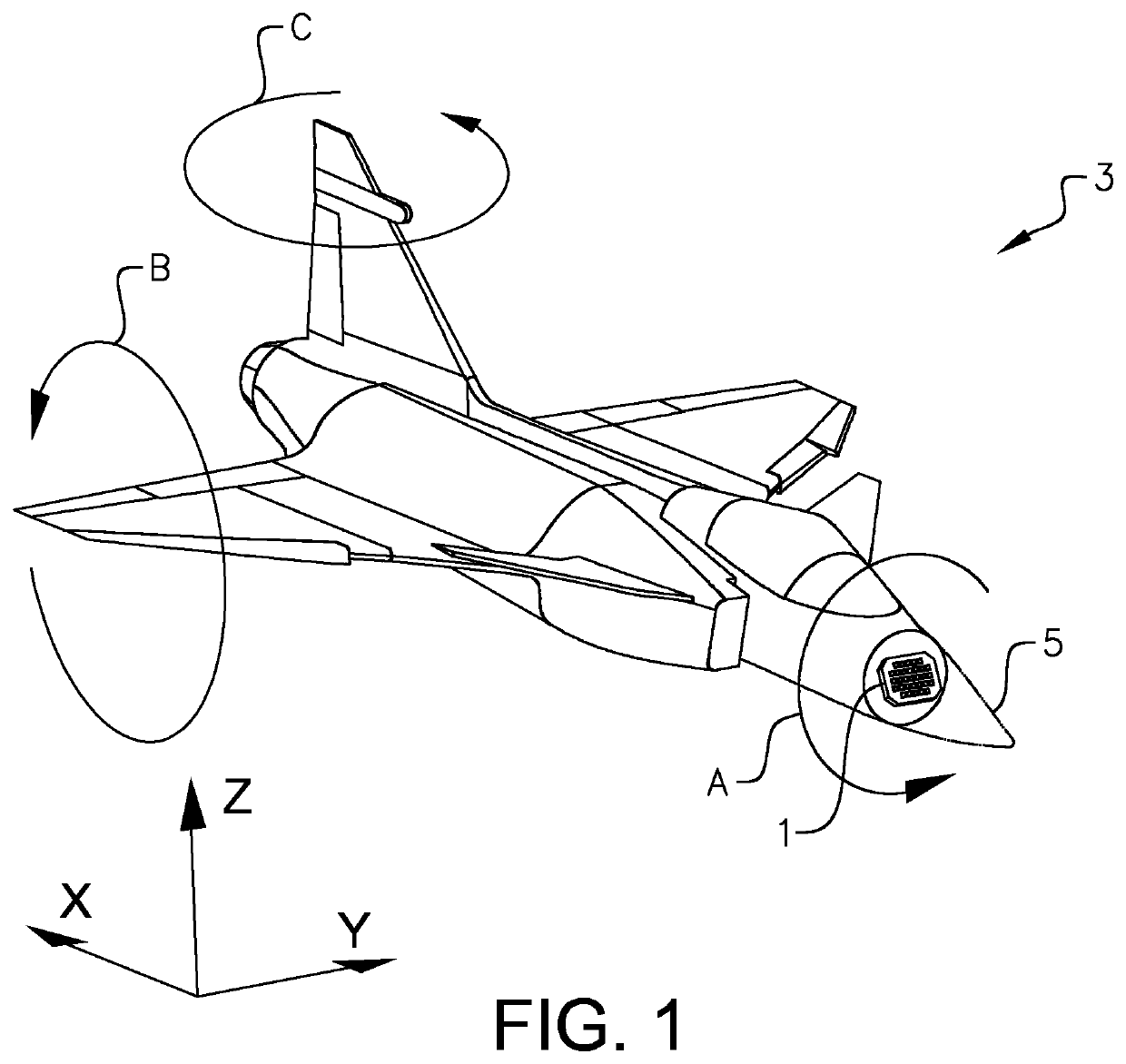
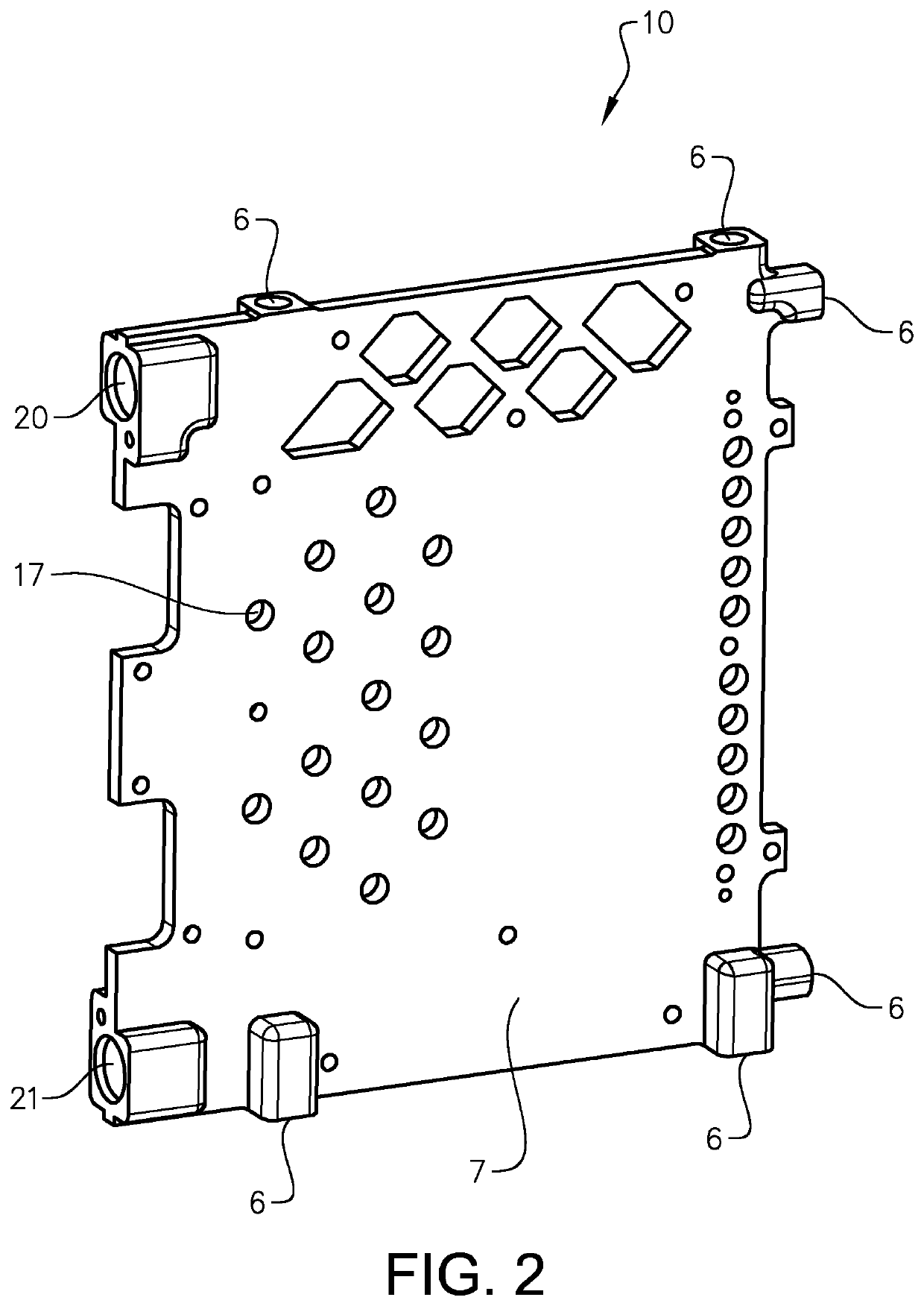
[0079]The following description of exemplary embodiments of the present invention is presented only for purposes of illustration and should not be seen as limiting. The description is not intended to be exhaustive and modifications and variations are possible in the light of the above teachings, or may be acquired from practice of various alternative embodiments of the present invention. The examples discussed herein were chosen and described in order to explain the principles and the nature of various exemplary embodiments and its practical application to enable one skilled in the art to utilize the exemplary embodiments in various manners, and with various modifications, as are suited to the particular use contemplated. It should be appreciated that the aspects presented herein separately may be practiced in any combination with each other unless otherwise explicitly is stated.

[0080]Reoccurring reference signs refer to corresponding elements throughout the detailed description. Wh...


PUM


Abstract

A cooling device for providing cooling capability of adjacent structures comprises a hollow chamber, an inlet and a chamber outlet, wherein the inlet, the chamber and the chamber outlet are configured such that fluid flow may enter via the inlet, pass through the chamber, and exit via the chamber outlet. The chamber is divided into a distribution chamber and a cooling chamber by a partitioning member, wherein the inlet is fluidly connected to the distribution chamber and the chamber outlet is fluidly connected to the cooling chamber. The partitioning member comprises at least a first and a second constriction passage, wherein the first constriction passage has a first predefined cross sectional flow area and the second constriction passage has a second predefined cross sectional flow area. The sizes of the predefined at least first and second cross sectional flow areas of the at least first and second constriction passages are controllable, whereby the distribution of fluid flow from the distribution chamber to the cooling chamber via the respective constriction passage is controllable.

Description

TECHNICAL FIELD[0001]The present disclosure relates to a cooling device for controlling the temperature of electronic components such as e.g. components of a circuit board. The present disclosure may e.g. be applied in electronically steerable antennas in order to control temperature of high power components. Although the present disclosure will be described with respect to an electrically steerable antenna, the present disclosure is not restricted to this particular use, but may also be used in other applications where temperature control of e.g. electrical components is required.BACKGROUND ART[0002]The increased use of electronically steerable antennas, generally referred to as AESAs (Active Electronically Scanned Arrays), involves new challenges e.g. in terms of cooling of e.g. circuit boards. The often complex design of AESAs has the effect that the availability of cooling fluid is restricted and that the flow rates often are relatively low. This combined with the fact that AESA...

Claims


Application Information

Patent Timeline
IPC IPC(8): F28F3/12F28F27/02H05K7/20
CPCF28F3/12F28F27/02F28F2240/00F28F2265/18H01Q1/02H05K7/20272B33Y80/00F28D9/0031F28F3/02F28F9/0263F28F9/028F28F13/02F28F13/08H01L23/473H01Q1/281H05K7/20254H01M10/613H01M10/653H01M10/6566H01M10/6568Y02E60/10
Inventor BLENNIUS, MARTINFALK, HANS
Owner SAAB AB
Why Eureka
Try Eureka