
Folding Walker with Wheels

Active Publication Date: 2019-12-19
DIEP GREG
View PDF0 Cites 0 Cited by
  • Summary
  • Abstract
  • Description
  • Claims
  • Application Information

AI Technical Summary

Benefits of technology

The patent describes three different folding walkers with wheels that support children. They are all adjustable to allow the child to move and change positions while using the walker. The walkers have a frame that can fold up for easy storage and transport. The folding support frame keeps the legs in place when used as a walker but can fold horizontally like a tent to save space. Overall, these folding walkers make it easier for childcare providers to transport and store equipment, and make it easier for children to move around while using the walker.

Problems solved by technology

Unfortunately, the standup play stations are rigid structures and not designed to be dissembled or broken down for easy transport in the back of a motor vehicle for use at a remote location, such as a daycare, a park, or a mall.

Method used


Image

  • Folding Walker with Wheels
  • Folding Walker with Wheels
  • Folding Walker with Wheels

Examples


first embodiment

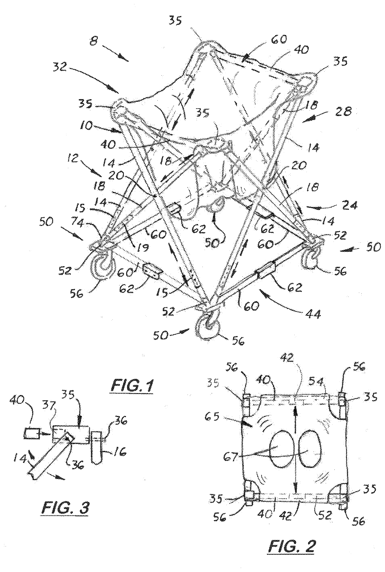
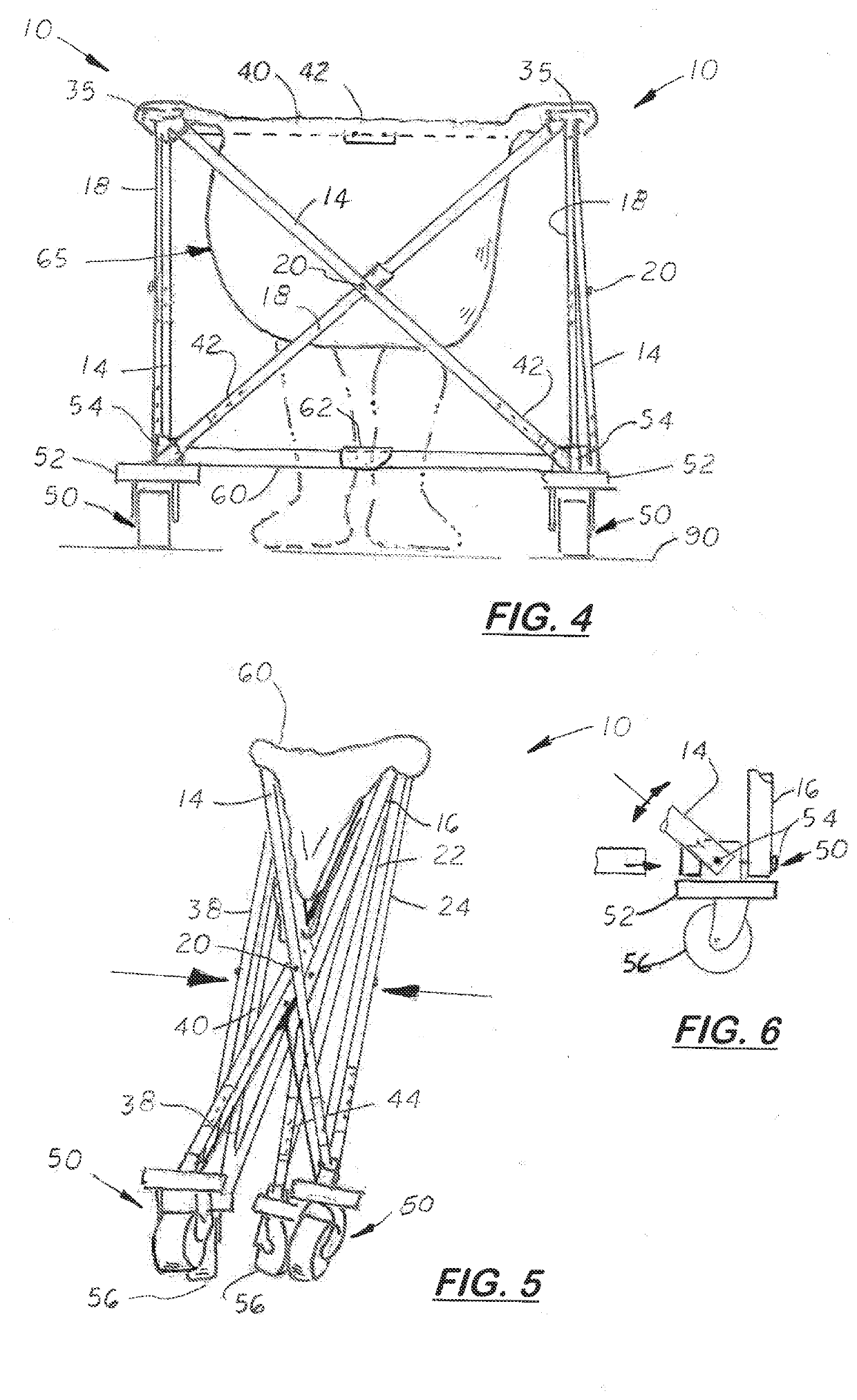
[0030]In the first embodiment, shown in FIGS. 1-3, the walker 8 uses a four-sided frame 10 that includes a four, collapsible and telescopically adjustable leg assemblies 12, 24, 28, and 32. The leg assemblies 12, 24, 28, and 32 are configured to stand vertically and are approximately 90 degrees apart. Each leg assembly 12, 24, 28 and 32 includes two diagonal frame members 14, 18 pivotally connected together via a centrally located pivoting peg 20 that allows the diagonal frame members 14, 18 to rotate relative to each other and extend as shown in FIG. 1 or collapse as shown in FIG. 5. FIG. 15 shows two diagonal members 14, 18 being connected together with a peg 20. An optional sleeve 22 is shown that provides added support.

[0031]The upper ends of the diagonal frame members 14, 18 connect to an upper corner cap 35 shown more clearly in FIG. 3. The upper ends of the two diagonal members 14, 18 are pivotally attached to the upper corner cap 35 with pegs 36 and allow the diagonal member...

second embodiment

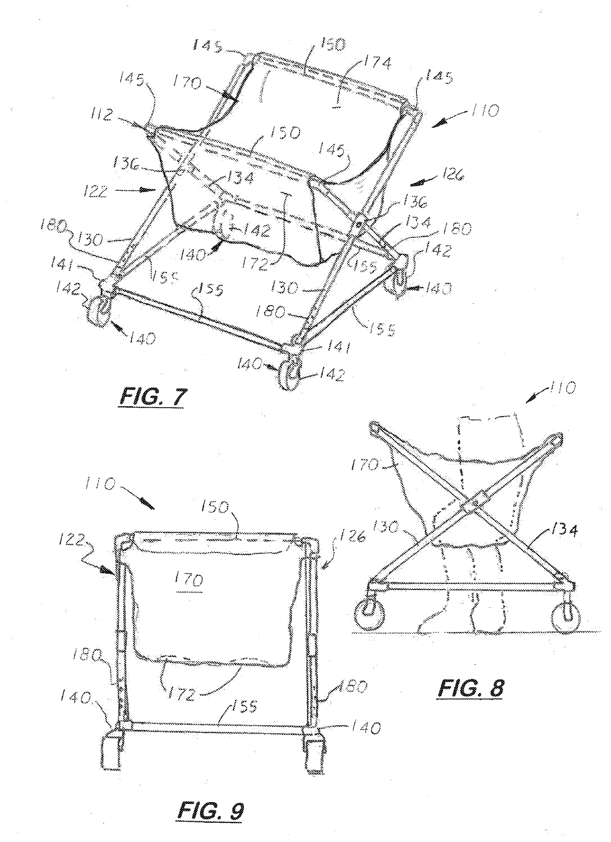
[0036]FIGS. 7-12 show the folding child walker 110 that includes folding frame 112 that includes a square-shaped lower frame structure 120 with four caster wheel assemblies 130 attached at each lower corner. Walker 110 is configured to collapse vertically.

[0037]The folding frame 112 includes two X-shaped leg assemblies 122 and 126. Each leg assembly 122, 126 includes two diagonal members 130 and 134. The two diagonal members 130 and 134 are coupled together by a coupler 136. The coupler 136 shown more clearly in FIG. 11 includes two pivoting cylindrical bodies 137, 138 connected with a center peg 139. During assembly, the diagonal members 130, 134 are inserted into the cylindrical bodes 137, 138, respectively. The cylindrical bodies 137, 138 can rotate and self-adjust around each other and adjust their orientations. Optional lock screws 139 may lock the couplers 136 to one or both diagonal members 130, 134.

[0038]Formed on each diagonal member 130, 134 is an optional telescopic joint...

third embodiment

[0042]FIGS. 13-17 show the walker 210 that includes a collapsible frame 212 with four telescopic vertical legs 222, 224, 226, and 228 and two or four collapsible side frames 230.

[0043]The each collapsing side frames 230 each include a folding upper member 232 and a folding lower member 240. The proximal ends of the folding members 232, 240 are pivotally attached to a vertical leg 222, 224, 226, 228. Each upper frame member 232 is made of two elongated sections joined by a locking collar 234 that holds distal ends of the elongated sections together in axial alignment. The locking collar 234 is pivotally attached at its opposite ends to the two elongated sections. When the locking collar 234 is forced upward, the two elongated sections are misaligned thereby enabling the legs 222, 224, 226 or 228 to move inward as shown in FIG. 15. On the front and rear side frames on the walker 210, a supplement locking assembly 250 is provided that locks the child walker in an expanded, unfolded con...


PUM


Abstract

A child's folding walker with caster wheels that is adjustable in height to permit a child to sit and touch the ground and move the walker. The walker includes four vertical legs, and upper platform that attaches to a suspended seat with leg holes configured to hold a sitting child in a suspended position above the floor. Attached to the distal ends of the legs is a rotating wheel. Disposed between the four legs is a folding support frame configured to hold the four legs in a fixed position when used as a walker but collapses into a folding configuration for compact storage and easy transport. In one embodiment, the walker includes four X-shaped leg assemblies that enable the walker to collapse into a compact vertical configuration. In another embodiment, the walker has two X-shaped leg assemblies that enable the walker to collapse into compact horizontal configuration. In a third embodiment, the walker has four vertical legs and two collapsible side frames that enabling the walker to collapse into a vertical configuration.

Description

[0001]This utility patent application is based on and claims the filing date benefit of U.S. provisional patent application (62 / 617,727) filed on Jan. 16, 2018.[0002]Notice is given that the following patent document contains original material subject to copyright protection. The copyright owner has no objection to the facsimile or digital download reproduction of all or part of the patent document, but otherwise reserves all copyrights.BACKGROUND OF THE INVENTION1. Field of the Invention[0003]This invention pertains infant walkers, and more particularly, to such walkers that include wheels and collapse for compact storage.2. Description of the Related Art[0004]Standup play stations for children that include a rigid lower base with four wheels and an elevated platform that supports a child seat are found in the prior art. The elevated platform is held in a fixed elevation above the lower base by four rigid legs. The play station's legs have holes that enable the height of seat to be...

Claims


Application Information

Patent Timeline
IPC IPC(8): A47D13/04
CPCA47D13/043A47D1/02
Inventor DIEP, GREG
Owner DIEP GREG
Learn More