
Vehicular roof structure

a technology for roofs and vehicles, applied in roofs, wing accessories, transportation and packaging, etc., can solve the problem that the conventional structure cannot be set to give a sense of spaciousness to the passenger in the rear seat, and achieve excellent effect, expand the range of daylighting, and give a sense of spaciousness

Inactive Publication Date: 2012-07-24
TOYOTA BOSHOKU KK
View PDF29 Cites 2 Cited by
  • Summary
  • Abstract
  • Description
  • Claims
  • Application Information

AI Technical Summary

Benefits of technology

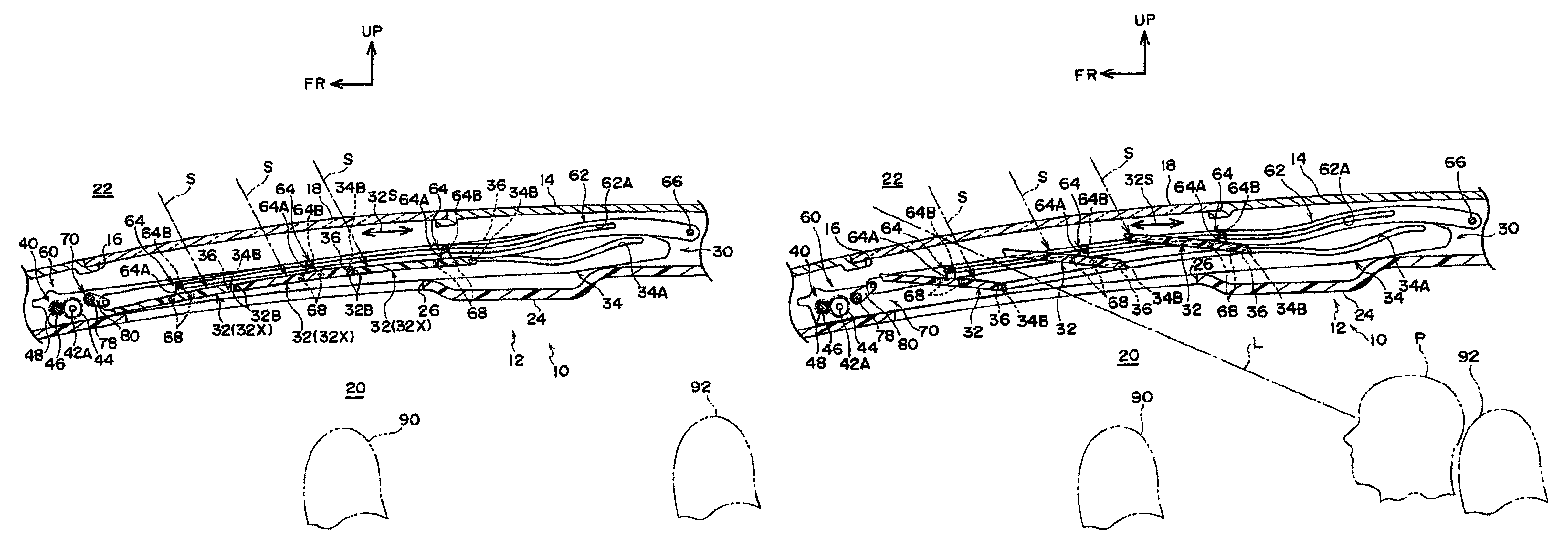
[0014]As described above, the vehicular roof structure according to the first aspect of the present invention has an excellent effect that it can adjust the quantity of daylighting and can be set to give a sense of spaciousness to a passenger in the rear seat by the wide field of view from the vehicular upper side while blocking the incident light to the front seat side.
[0015]The vehicular roof structure according to the second aspect of the present invention has an excellent effect that it can expand the range of the quantity of daylighting that is adjustable, and can compactly store the light blocking members.
[0016]The vehicular roof structure according to the third aspect of the present invention has an excellent effect that the light blocking members can be moved backward and forward along the pair of guide rails, and the angles of inclination of the light blocking members can be changed while being supported by the pair of guide rails.
[0017]The vehicular roof structure according to the fourth aspect of the present invention has an excellent effect that the angles of inclination of the light blocking members can be changed simultaneously by using a relatively simple structure.

Problems solved by technology

However, the aforementioned conventional structure cannot be set to give a sense of spaciousness to a passenger in the rear seat by the wide field of view from the vehicular upper side while blocking the incident light to the front seat side.Patent document 1: Japanese Patent Application Laid-Open (JP-A) No. 2007-22219

Method used


Image

  • Vehicular roof structure
  • Vehicular roof structure
  • Vehicular roof structure

Examples


Embodiment Construction

Configuration of Exemplary Embodiments

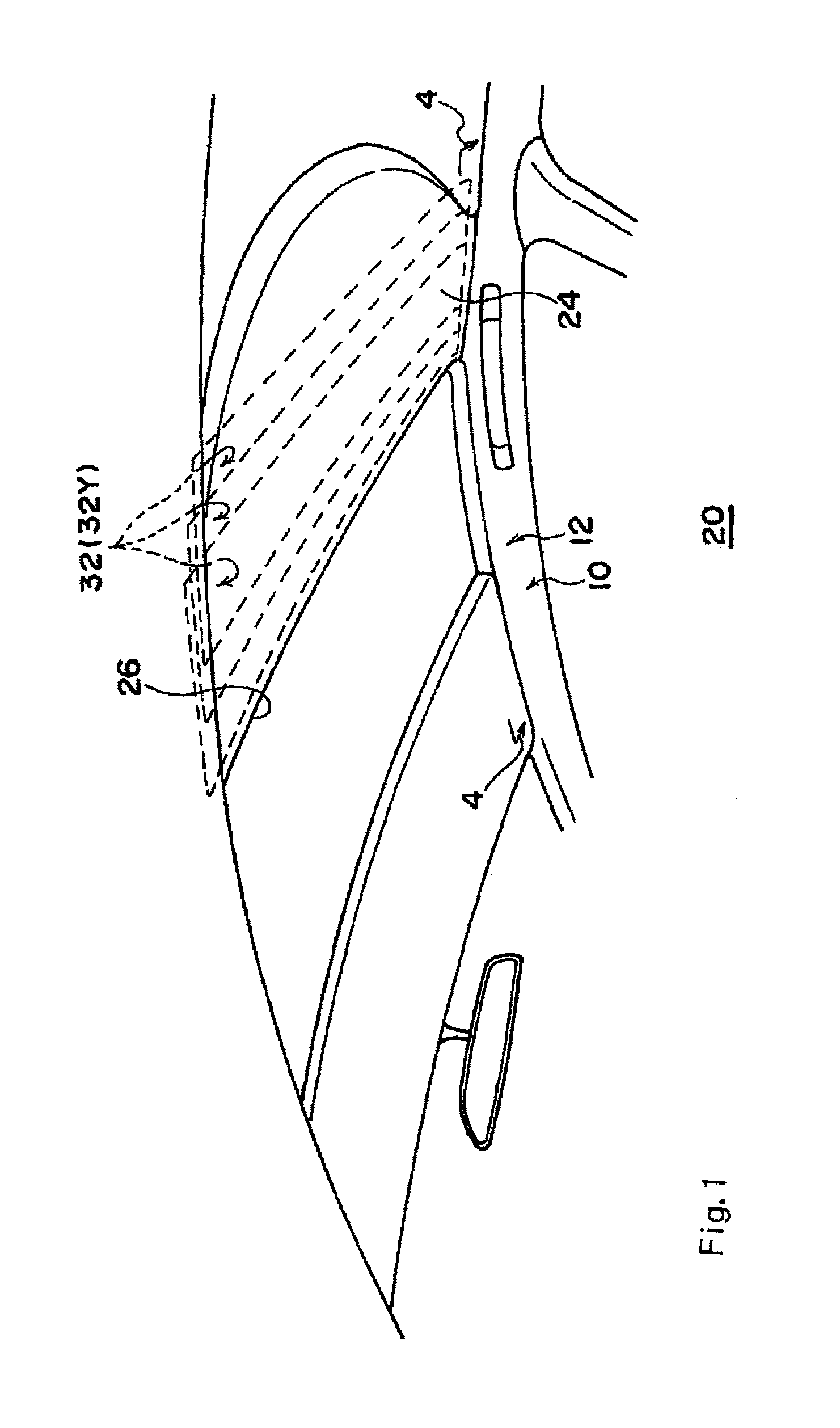
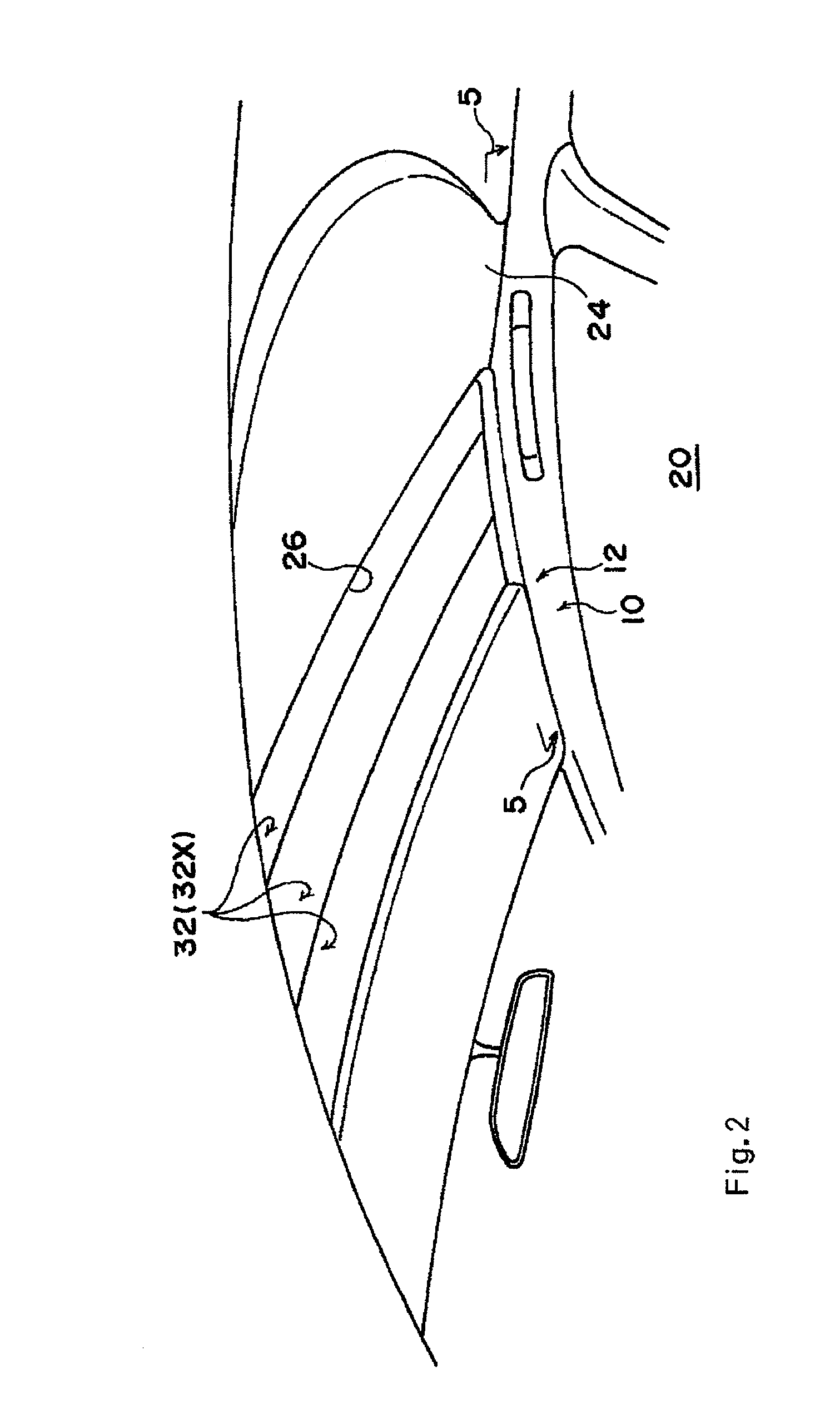
[0027]An exemplary embodiment of the vehicular roof structure according to the present invention is explained using FIGS. 1 through 9. Note that in these figures, the upward direction of the vehicle is indicated by the UP arrow, the front side of the vehicle is indicated by the FR arrow, and the widthwise direction of the vehicle is indicated by the W arrow. Further, in the present embodiment, the upward direction of the vehicle is the same as the upper side of the vehicular roof.

[0028]FIGS. 1 to 3 show the appearance of the upper section of the vehicle interior. As shown in these figures, a vehicle-body upper portion 10 is provided with a vehicular roof (daylighting roof) 12 which can adjust the quantity of daylighting by operation of a passenger, and the vehicular roof 12 is provided with louvers (louver vanes) 32 (see FIGS. 2 and 3, the louvers are described later in detail) each serving as a light blocking member which can open and close. FI...


PUM


Abstract

Provided is a vehicular roof structure, which can adjust the quantity of daylighting and which can be set to give a sense of spaciousness to a passenger in the rear seat by the wide field of view from the vehicular upper side while blocking the incident light upon the front seat side. Three louvers are enabled to change their angles of inclination with respect to the longitudinal direction of the vehicle. If the individual louvers arranged at the blocking positions are oriented to slope in a slightly downward direction of the vehicle toward the rear side thereof, a passenger in a rear seat can see, while an incident light to the front seat side is being blocked by the three louvers, the outside of the upper side of the vehicle through the three inclined louvers.

Description

TECHNICAL FIELD[0001]The present invention relates to a vehicular roof structure that is capable of admitting daylight through an opening portion of a roof panel.BACKGROUND ART[0002]There are cases in which a vehicular roof has an opening portion formed therein for daylighting. In this kind of vehicular roof, in order to adjust the quantity of daylighting, for example, a plurality of roof shades arranged at the opening portion are made movable so as to open and close in the state of being connected together or being separated from one another (for example, refer to patent document 1).[0003]However, the aforementioned conventional structure cannot be set to give a sense of spaciousness to a passenger in the rear seat by the wide field of view from the vehicular upper side while blocking the incident light to the front seat side.[0004]Patent document 1: Japanese Patent Application Laid-Open (JP-A) No. 2007-22219DISCLOSURE OF THE INVENTIONProblems to be Solved by the Invention[0005]In ...

Claims


Application Information

Patent Timeline
Patent Type & Authority Patents(United States)
IPC IPC(8): B60J3/02B60J7/00
CPCB60J7/003
Inventor HIRAI, SHINJIYASUDA, HITOSHI
Owner TOYOTA BOSHOKU KK
Learn More