Support structures for hanging equipment

a technology for supporting structures and equipment, applied in the direction of dismountable cabinets, instruments, cycle stands, etc., can solve the problems of reducing the service life of volunteers, and restraining volunteers to carry heavy objects, etc., to achieve the effect of improving the structure of racking devices, simple design and construction, and efficient and robus

Active Publication Date: 2013-11-07
MOVED BY BIKES
View PDF30 Cites 0 Cited by
  • Summary
  • Abstract
  • Description
  • Claims
  • Application Information

AI Technical Summary

Benefits of technology

[0006]The main telescoping tubes can be locked together with small push button assemblies in that can be unlocked by hand. The “legs” can have end caps on either end, and may be smaller at one end so that they only slide to a predetermined distance into the main tubes. The legs may be designed to fit inside the main telescoping tubes, making for extremely compact storage of the assembly. For transportation, the legs can be secured inside the main tubes with a small cap, pin, or other means (e.g., the end of a bag that also protects the rack from abrasion). The legs can be set in from the end of the tubes, shortening the span of the main tubes (improving strength) and allowing for a bicycle or similar equipment to be supported on the end of the rack, which can provide easier access than having all equipment to the inside of the legs as is currently seen in this market.
[0008]The proposed system, method and device can offer, among other advantages, an improved structure for racking devices, such as bicycles. In other embodiments, the device can provide banner and signage space. This can be accomplished in an efficient and robust manner compared to other systems. Advantageously, the proposed system, method and device can be packed into itself for a packed size and weight that are extremely lightweight. The simple design and construction means that the assembly can be produced at a low cost. These and other advantages of the present invention will become apparent to those skilled in the art upon a reading of the following descriptions and a study of the several figures of the drawings.

Problems solved by technology

Coming up with a design that achieves all of these goals is a major improvement for the industry, which currently lacks a good solution to meet these requirements.
In many cases, groups are resorting to traditional means that are heavy and very difficult for volunteers to transport.
Other limitations of the related art will become apparent to those of skill in the art upon a reading of the specification and a study of the drawings.

Method used


Image

  • Support structures for hanging equipment
  • Support structures for hanging equipment
  • Support structures for hanging equipment

Examples


Embodiment Construction

[0022]Embodiments of the inventions are illustrated in the figures. However, the embodiments and figures are illustrative rather than limiting; they provide examples of the invention. As used herein, the term “embodiment” means an embodiment that serves to illustrate by way of example but not limitation.

[0023]Moreover, in the following description, several specific details are presented to provide a thorough understanding of embodiments of the invention. One skilled in the relevant art will recognize, however, that the invention can be practiced without one or more of the specific details, or in combination with other components, etc. In other instances, well-known implementations or operations are not shown or described in detail to avoid obscuring aspects of various embodiments, of the invention.

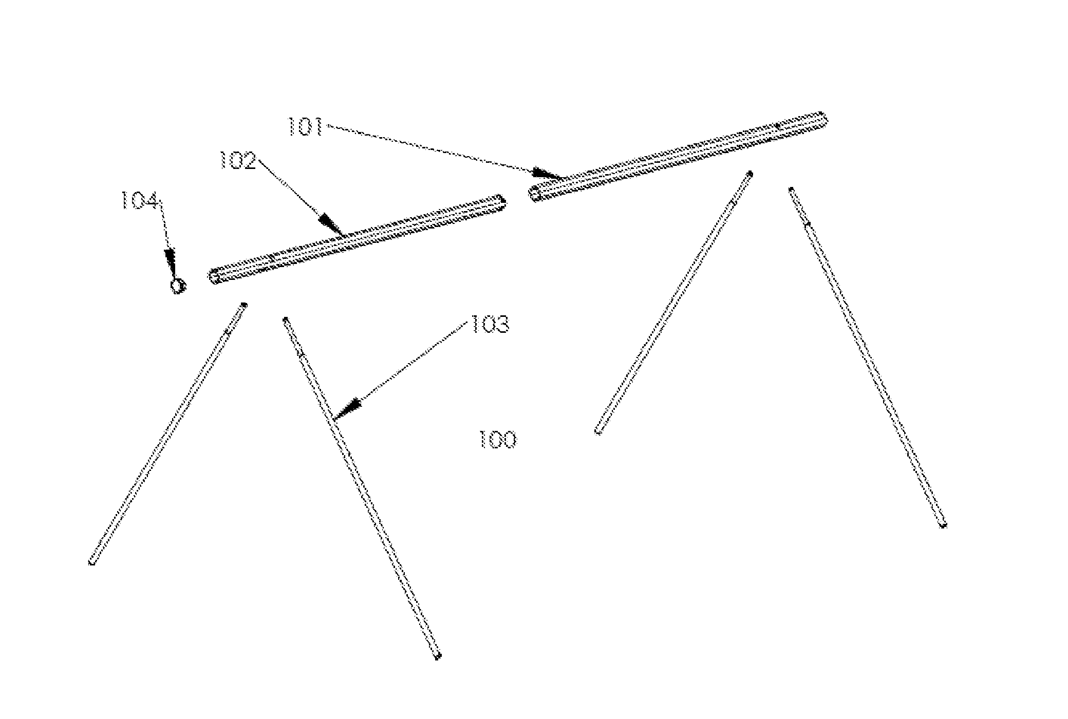
[0024]FIG. 1 shows an exploded perspective view a complete rack assembly 100 for hanging equipment in accordance with some embodiments. Complete rack assembly 100 can include a main outer ...


PUM


Abstract

Described herein is a new assembly of components which comprise a support structure for hanging or supporting bicycles or similar equipment. The rack is designed using a number of tubes that pack into themselves for an extremely compact, lightweight assembly which is very easy to transport and store. The simple design ensures long term reliability and ease of use.

Description

CROSS-REFERENCE TO RELATED APPLICATIONS[0001]This application claims the benefit of U.S. Provisional Application No. 61 / 643,833, filed May 7, 2012, which is incorporated by reference herein in its entirety.BACKGROUND OF THE DISCLOSURE[0002]Event racks for storage of equipment, such as bicycles and other devices are becoming increasingly in demand as more and more people use bicycles for transportation and recreation. Racks for parking bicycles in particular are in demand at sporting events including triathlons, biathlons, and bike races and tours where there is a need to park a large number of bicycles that do not have kickstands or other means to support themselves. Another common need for these types of racks is at public events such as concerts, festivals, or stadium events such as football games, where there is a need to park and secure a large number of bicycles or similar equipment in a small space and with minimal equipment. The key features that make a design viable in this ...

Claims


Application Information

Patent Timeline
Patent Type & Authority Applications(United States)
IPC IPC(8): A47B47/00B62H3/00
CPCA47B47/00B62H3/00G09F15/00E04G1/32
Inventor MCPHEETERS, GREG
Owner MOVED BY BIKES
Why Eureka
Try Eureka