Centrifugal Pump Having a Radial Impeller

Active Publication Date: 2019-12-26
KSB AG
View PDF0 Cites 0 Cited by
  • Summary
  • Abstract
  • Description
  • Claims
  • Application Information

AI Technical Summary

Benefits of technology

[0019]Consequently, in this variant, as seen from the suction side, firstly the split ring seal arrangement with a split ring and with a running ring between the cover shroud and the casing part is provided, and subsequently the volume flow discharged through the channel enters the radial sealing gap, which is formed between the cover shroud and a casing part. This is very advantageous in terms of rotor dynamics since, in this way, the damping in the sealing gap is increased.
[0020]The diversion of the angular momentum flow results in the rotation of the fluid in the front impeller

Problems solved by technology

Such conventional plate constructions for reducing the axial thrust are susceptible to faults and a

Method used


Image

  • Centrifugal Pump Having a Radial Impeller
  • Centrifugal Pump Having a Radial Impeller
  • Centrifugal Pump Having a Radial Impeller

Examples


Example

DETAILED DESCRIPTION OF THE DRAWINGS

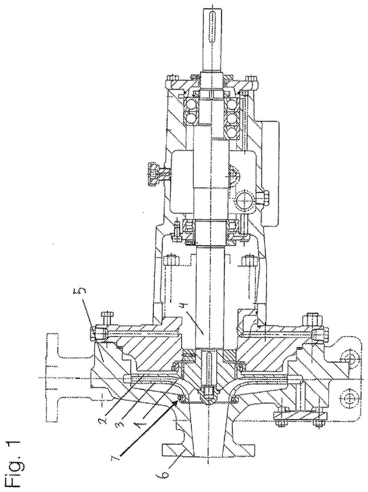
[0029]FIG. 1 shows a centrifugal pump with an impeller 1. The impeller 1 is designed in the form of a closed radial impeller and has a rear shroud 2 and cover shroud 3. Vanes are arranged on the rear shroud 2. Passages for delivering the medium are formed between the rear shroud 2 and the cover shroud 3. The impeller 1 is driven by a shaft 4. The impeller 1 is surrounded by a casing 5 which may be of multi-piece design. The casing 5 has a suction mouth 6. The centrifugal pump has a split ring seal arrangement 7. The split ring seal arrangement 7 delimits the gap volume flow which flows from the pressure region of the centrifugal pump back into the suction region. The impeller 1 is designed in the form of a radial impeller. The fluid flows to the impeller 1 in an axial direction and is then diverted through 90° and then exits the impeller 1 in a radial direction.

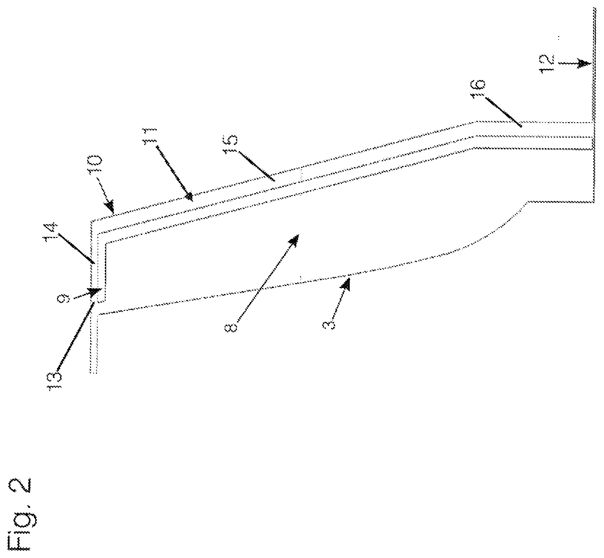
[0030]FIG. 2 shows a schematic illustration of the front impeller side space 8 which is...


PUM


Abstract

A centrifugal pump includes a radial impeller surrounded by a housing. The housing has a channel associated with a front side space between a cover of the impeller and the casing. Flow is led through the channel from a pressure region of the pump to a radial gap at a suction region of the pump. The flow in the channel reduces angular momentum and results in an increase in pressure in the front side space which acts of in the cover side of the impeller to offset axial force from a rear side of the impeller.

Description

CROSS REFERENCE TO RELATED APPLICATIONS[0001]This application is a continuation of PCT International Application No. PCT / EP2017 / 081448, filed Dec. 5, 2017, which claims priority under 35 U.S.C. § 119 from German Patent Application No. 10 2016 225 018.3, filed Dec. 14, 2016, the entire disclosures of which are herein expressly incorporated by reference.BACKGROUND AND SUMMARY OF THE INVENTION[0002]The invention relates to a centrifugal pump having a radial impeller which is surrounded by a casing.[0003]Owing to their design, in radial centrifugal pumps, a resultant axial force on the rotor occurs, which has to be compensated. Here, main components of said axial force are the pressure forces acting on the cover shroud and the rear shroud, which pressure forces are directed oppositely to one another. Generally, the force acting on the rear shroud is significantly greater than the component acting on the cover shroud, with the result that an axial thrust directed on the suction side occu...

Claims


Application Information

Patent Timeline
IPC IPC(8): F04D29/42F04D29/16
CPCF04D29/426F04D29/167F04D29/0416
Inventor WILL, BJOERN
Owner KSB AG
Why Eureka
Try Eureka