Illumination device and projector

a technology of projector and light source, which is applied in the direction of projector, optics, instruments, etc., can solve the problems of increasing light loss caused in the red laser beam and increasing light loss caused in the fluorescen

Active Publication Date: 2019-12-26
SEIKO EPSON CORP
View PDF0 Cites 9 Cited by
  • Summary
  • Abstract
  • Description
  • Claims
  • Application Information

AI Technical Summary

Problems solved by technology

Here, when, for example, increasing the transmittance of the combining mirror for the red component included in the fluorescence, the red laser beam transmitted through the combining mirror increases, and thus, the light loss caused in the red laser beam increases.
In contrast, when, for example, increasing the reflectance of the combining mirror for the red laser beam, an amount of the red component included in the fluorescence and reflected by the combining mirror increases, and thus, the light loss caused in the fluorescence increases.

Method used


Image

  • Illumination device and projector
  • Illumination device and projector
  • Illumination device and projector

Examples


first embodiment

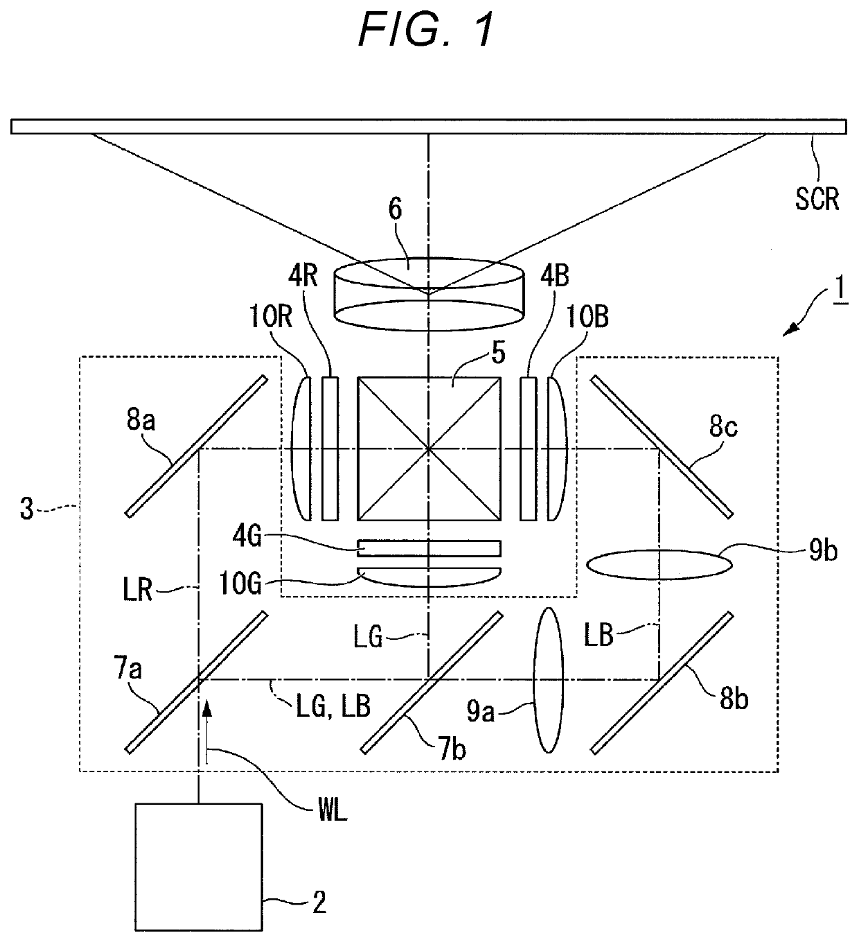
[0022]FIG. 1 is a schematic configuration diagram of a projector according to the present embodiment.

[0023]As shown in FIG. 1, the projector 1 according to the present embodiment is a projection-type image display device for displaying a color image on a screen SCR. The projector 1 is provided with an illumination device 2, a color separation optical system 3, a light modulation device 4R, a light modulation device 4G, a light modulation device 4B, a combining optical system 5, and a projection optical system 6.

[0024]The illumination device 2 according to the present embodiment emits white illumination light WL toward the color separation optical system 3. The color separation optical system 3 separates the illumination light WL from the illumination device 2 into red light LR (e.g., light in a wavelength band of 600 nm through 700 nm), green light LG (e.g., light in a wavelength band of 500 nm through 600 nm), and blue light LB (e.g., light in a wavelength band of 440 nm through 47...

second embodiment

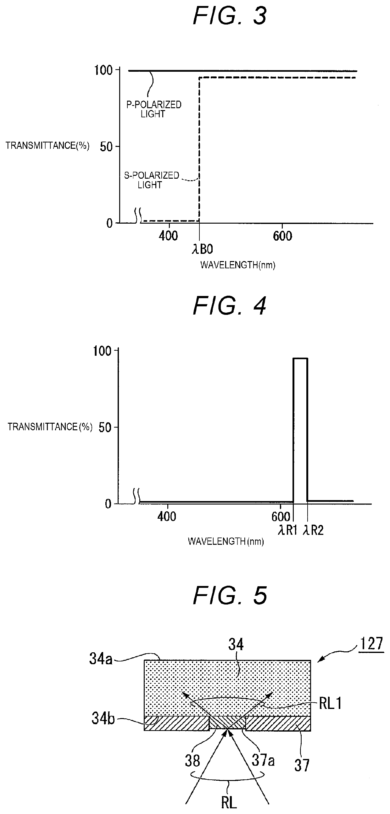
[0086]Then, an illumination device according to a second embodiment of the present disclosure will be described. The present embodiment and the embodiment described above are difference from each other only in the configuration of the fluorescence emitting element, and are the same in the other configurations. Therefore, in the following description, the configuration of the fluorescence emitting element will mainly be described, the members common to the present embodiment and the embodiment described above will be denoted by the same reference symbols, and the detailed description thereof will be omitted.

[0087]FIG. 5 is a cross-sectional view showing the configuration of the fluorescence emitting element related to the present embodiment. As shown in FIG. 5, the fluorescence emitting element 127 of the present embodiment has the phosphor and a reflecting mirror (a reflecting film) 37. The reflecting mirror 37 has an opening 37a for transmitting the red supplementary light beams RL...

modified examples

[0095]As the fluorescence emitting element 127 of the present embodiment, there is described a so-called stationary type in which the phosphor to be irradiated with the excitation light does not move, but it is also possible to adopt a so-called rotary type in which the phosphor to be irradiated with the excitation light rotates.

[0096]FIG. 6 is a cross-sectional view showing a configuration of a fluorescence emitting element related to a modified example of the second embodiment. FIG. 7 is a plan view showing a configuration of the fluorescence emitting element related to the modified example of the second embodiment. It should be noted that FIG. 7 is a plan view of the fluorescence emitting element viewed from a bottom surface side.

[0097]As shown in FIG. 6 and FIG. 7, the fluorescence emitting element 127A of the present modified example has a substrate 52 having a light transmissive property and shaped like a disk rotated by a motor 51, a phosphor 34 disposed to have a ring-like s...


PUM


Abstract

An illumination device includes a blue laser emitting element, a red laser emitting element, a diffusely reflecting element configured to diffuse and reflect a part of light from the blue laser emitting element, a phosphor, a bandpass filter provided to the phosphor to transmit light from the red laser emitting element, a polarization splitting / combining element having a polarization split function, and a first wave plate disposed between the polarization splitting / combining element and the diffusely reflecting element. The polarization splitting / combining element guides a blue first polarization component to the diffusely reflecting element and guides a blue second polarization component to the phosphor. Then, the polarization splitting / combining element combines the fluorescence, the light from the red laser emitting element entering a second surface of the phosphor and then emitted from a first surface, and blue diffused light with each other to generate illumination light.

Description

[0001]The present application is based on, and claims priority from JP Application Serial Number 2018-119078, filed Jun. 22, 2018, the disclosure of which is hereby incorporated by reference herein in its entirety.BACKGROUND1. Technical Field[0002]The present disclosure relates to an illumination device and a projector.2. Related Art[0003]In recent years, there is a technology of generating illumination light by combining a blue laser beam and fluorescence generated by excitation with the blue laser beam with each other as a light source device used for a projector. For example, in JP-A-2016-224304, there is disclosed a light source device which combines yellow fluorescence, a blue laser beam and a red laser beam with each other and then emits the result.[0004]In the illumination device described above, the fluorescence is transmitted through a combining mirror and the red laser beam is reflected by the combining mirror, and thus the two light beams are emitted in the same direction...

Claims


Application Information

Patent Timeline
Patent Type & Authority Applications(United States)
IPC IPC(8): G03B21/20G02B27/28
CPCG02B27/283G03B21/208G03B21/2066G03B21/204G03B21/2073G03B21/2093G03B33/12G03B21/20
Inventor UCHIYAMA, SHOICHI
Owner SEIKO EPSON CORP
Why Eureka
Try Eureka