Stranded cable wedge

a technology of stranded cables and wedges, which is applied in the direction of cables, mechanical equipment, ropes and cables for vehicles/pulleys, etc., can solve the problems of reducing the anchoring performance of the rope placement tool, affecting the anchoring performance of the rope, so as to prevent the above-mentioned nipping damage and prevent the damage of the stranded cabl

Inactive Publication Date: 2020-01-02
TOKYO ROPE MFG +1
View PDF0 Cites 5 Cited by
  • Summary
  • Abstract
  • Description
  • Claims
  • Application Information

AI Technical Summary

Benefits of technology

[0010]An object of the present invention is to prevent damage to a stranded cable (a twisted memb...

Problems solved by technology

If, in a case where the gaps between the mutually adjacent split members are narrowed further by continuing the application of the tensile force, portions of the rope protrude into the gaps, the protruding por...

Method used


Image

  • Stranded cable wedge
  • Stranded cable wedge
  • Stranded cable wedge

Examples


Embodiment Construction

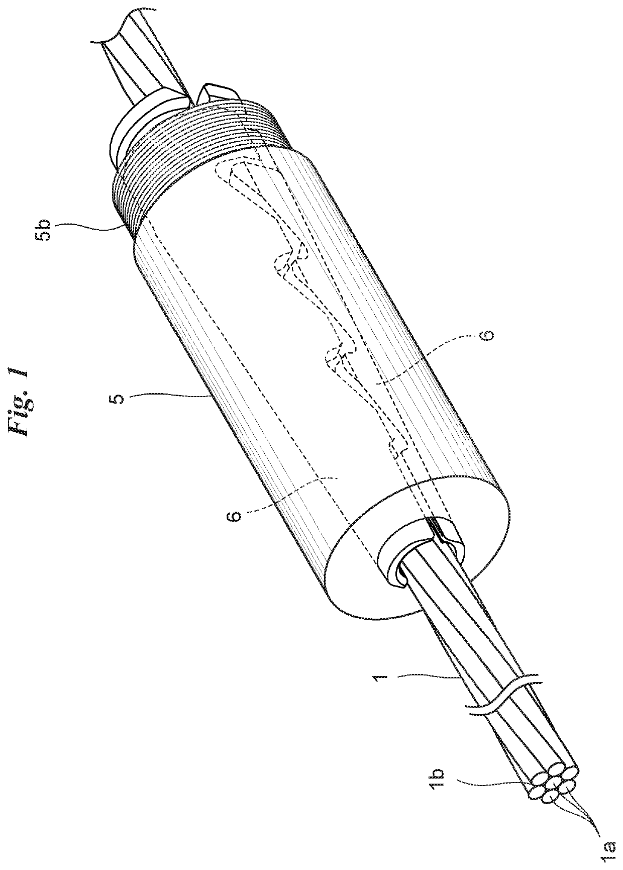
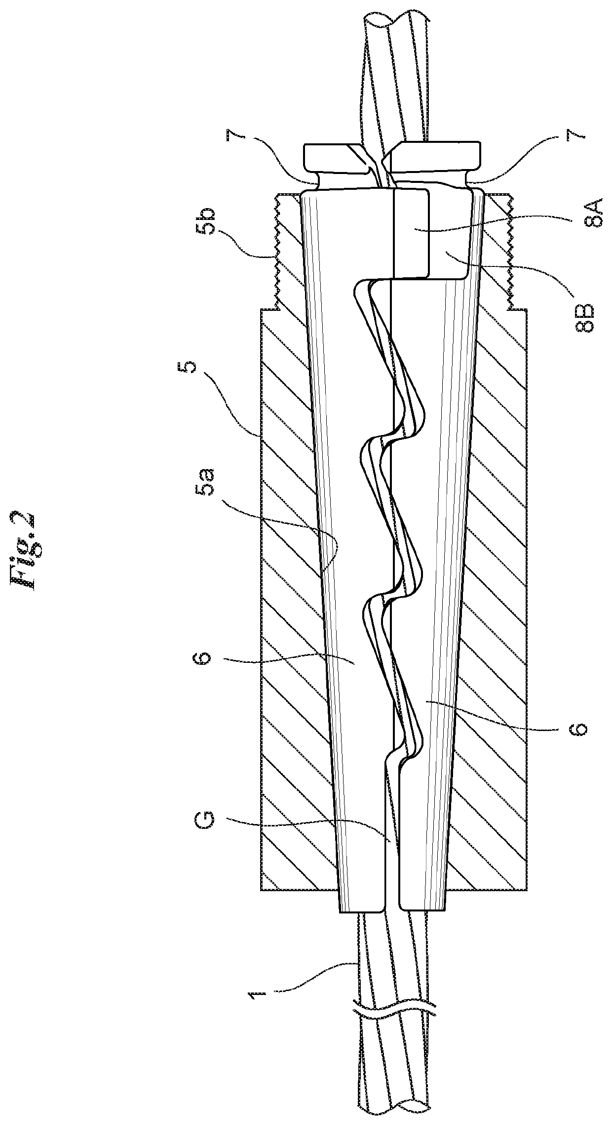
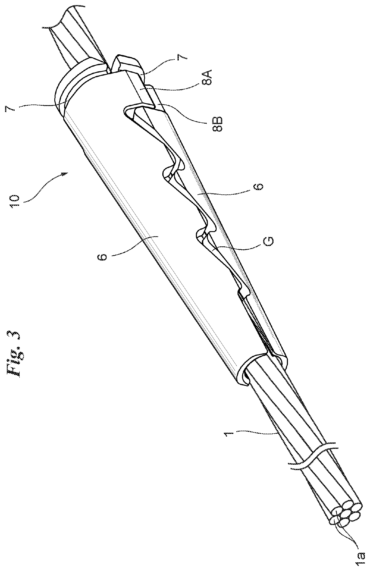
[0035]FIG. 1 is a perspective view illustrating an embodiment in which a terminal anchoring structure is applied to a terminal end portion of a cable 1 made of carbon fiber reinforced plastic (CFRP) (referred to also as a Carbon Fiber Composite Cable) (referred to as a CFRP cable below). FIG. 2 is a longitudinal sectional view of the terminal anchoring structure. FIG. 3 is a perspective view illustrating the manner in which two split wedge bodies have been attached to a terminal end portion of the CFRP cable 1, and FIG. 4 is an exploded perspective view thereof. FIG. 5 is a side view when two split wedge bodies have been attached to a terminal end portion of the CFRP cable 1. FIGS. 6 to 8 are enlarged sectional views taken along lines VI-VI, VII-VII, VIII-VIII of FIG. 5, respectively.

[0036]With reference to FIGS. 1 and 6, the CFRP cable 1 has a 1×7 structure obtained by twisting together seven carbon fiber bundles 1a, which are made of carbon fiber reinforced plastic and have a circ...


PUM

PropertyMeasurementUnit
Angleaaaaaaaaaa
Angleaaaaaaaaaa
Lengthaaaaaaaaaa

Abstract

A split wedge body, which has a curved inner surface, is formed gradually thicker from a tip portion to a terminal end portion thereof, and is made to cover the outer peripheral surface of a CFRP cable to thereby enclose the outer peripheral surface of the CFRP cable over a prescribed length thereof. A gap extending in the longitudinal direction is assured between end faces that oppose each other when a plurality of the split wedge bodies are arranged on the outer peripheral surface of the CFRP cable. The gap has an inclined portion that runs along a valley of the CFRP cable enclosed by the split wedge bodies.

Description

CROSS REFERENCE TO RELATED APPLICATIONS[0001]This application is a Continuation Application of PCT International Application No. PCT / JP2017 / 010243 filed on Mar. 14, 2017, the entire disclosure of the application being considered part of the disclosure of this application and hereby incorporated by reference.TECHNICAL FIELD[0002]This invention relates to a stranded cable wedge.BACKGROUND ART[0003]Prestressed concrete, in which compressive stress is applied to concrete by a pre-tension or post-tension method, is known in the art. Prestressed concrete is strong not only against compression but also tension and is employed widely in the field of public works, construction and bridge-building.[0004]To achieve the compressive stress applied to prestressed concrete, use is made of the reaction of tensile force applied to a tendon embedded in the concrete. In order to tension the tendon, it is necessary to grip the terminal end of the tendon stably and strongly, and it is required that a te...

Claims


Application Information

Patent Timeline
IPC IPC(8): E04C5/12
CPCE04C5/122D07B9/00F16G11/04E04C5/085
Inventor HACHISUKA, SHUNJIKIMURA, HIROSHIMANABE, DAISUKESHIMMURA, HIROYUKIKITADA, YUKIOYAMASHITA, RYO
Owner TOKYO ROPE MFG
Why Eureka
Try Eureka