
Electrical connection assembly and method for manufacturing same

Active Publication Date: 2020-01-09
AUTONETWORKS TECH LTD +2
View PDF1 Cites 1 Cited by
  • Summary
  • Abstract
  • Description
  • Claims
  • Application Information

AI Technical Summary

Benefits of technology

The present invention provides an electrical connection assembly with wires and connectors that can connect desired wires easily and without significant cost increase. Additionally, the invention provides a method to efficiently manufacture the electrical connection assembly. The invention also allows for the formation of a mutually connecting member with two terminals having bulging portions that can be integrated by heating, which ensures high reliability even at a distance between the terminals.

Problems solved by technology

However, any of the methods (i) to (iii) requires special component(s) dedicated for mutual connection different from the terminals with a normal specification and a considerable cost increase is inescapable.
Further, in terms of manufacturing, the methods (i) and (iii) are accompanied by a considerable increase of man-hours, and the method (ii) is accompanied by the complication of the management of the terminals including the special terminals.
Any of these hinders an improvement of production efficiency.

Method used


Image

  • Electrical connection assembly and method for manufacturing same
  • Electrical connection assembly and method for manufacturing same
  • Electrical connection assembly and method for manufacturing same

Examples


first embodiment

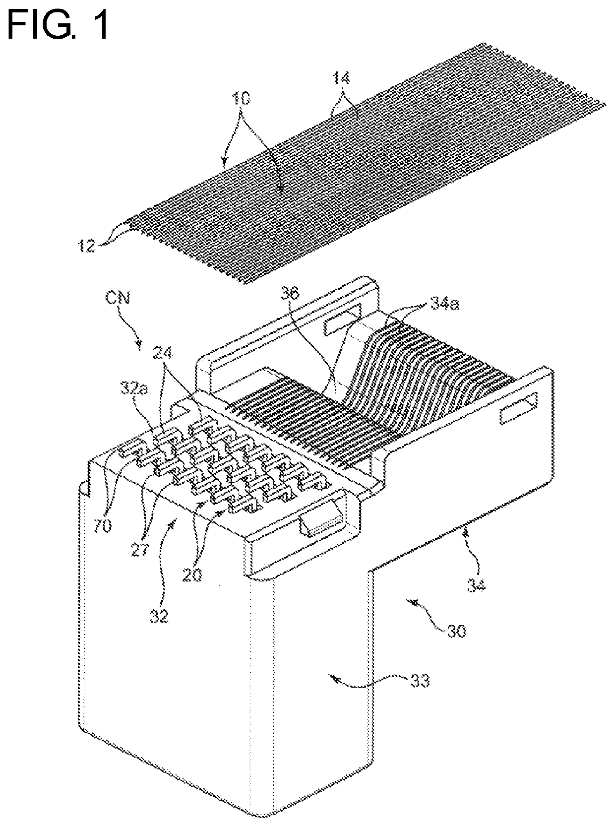
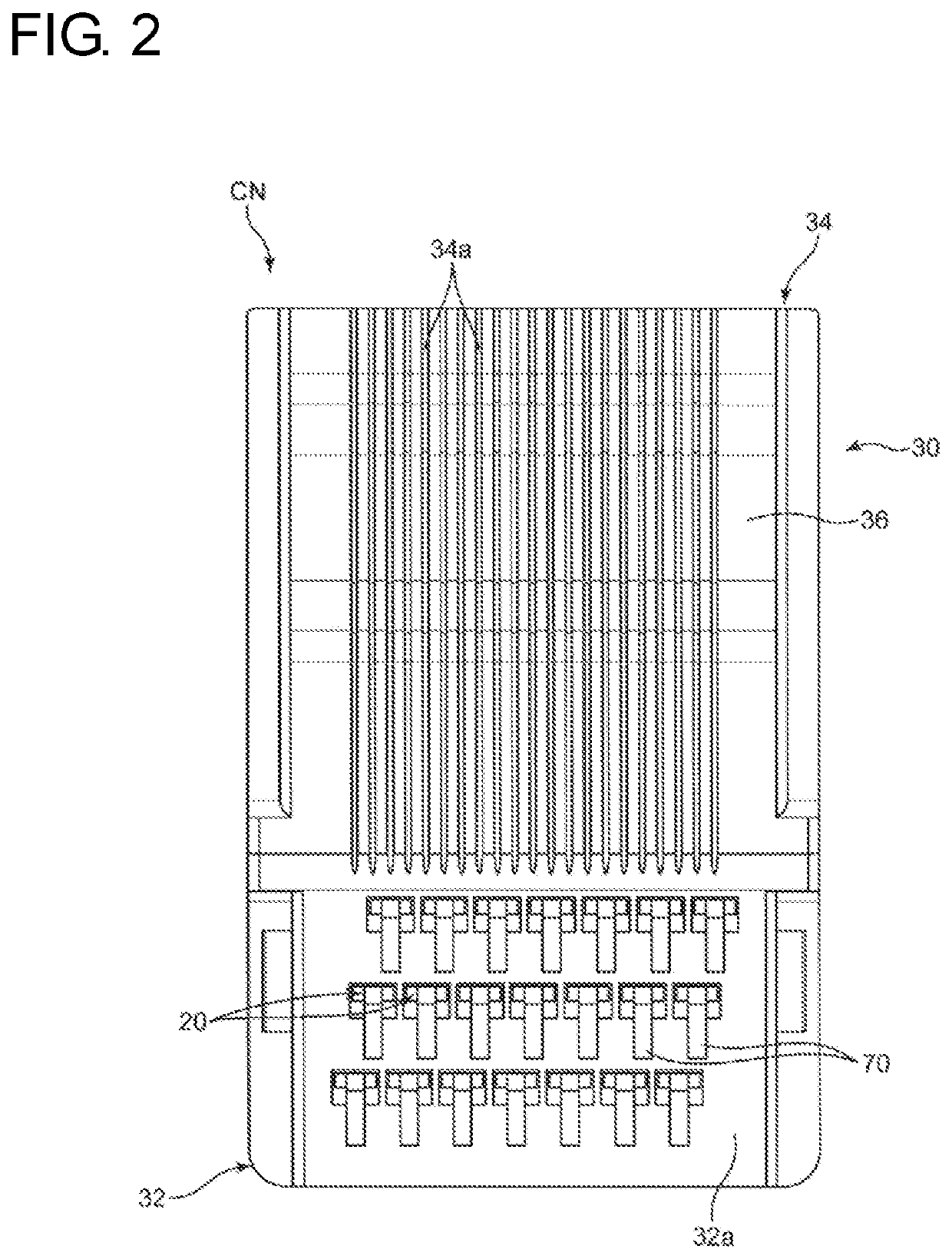
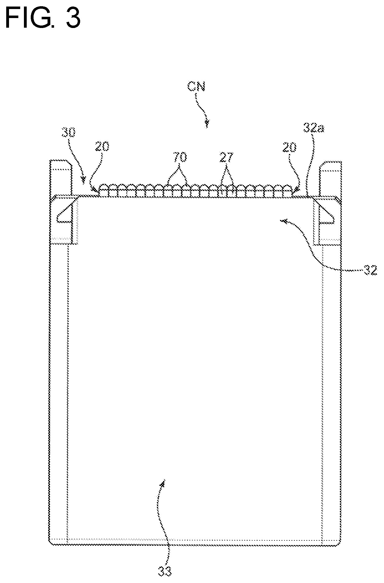
[0049]FIGS. 1 to 16 show an electrical connection assembly and a manufacturing method therefor according to the invention. The electrical connection assembly includes wires 10 and a connector CN for connecting the plurality of wires 10 to another connector. FIGS. 1 to 3 show the connector CN before the wires 10 are connected.

[0050]Each of the wires 10 includes a conductor 12 and an insulation coating 14 covering the conductor 12, as shown in FIGS. 10 and 13. The wires 10 are connected to the connector CN while being arranged in parallel to each other at intervals in a wire arrangement direction orthogonal to a longitudinal direction of the wires 10. The wires used in the present invention may be bare wires without the insulation coatings 14.

[0051]The wires 10 include a first wire 10A and a second wire 10B, as shown in FIGS. 9 and 10. These first and second wires 10A, 10B are adjacent in the wire arrangement direction and are to be connected electrically to each other to constitute a...

second embodiment

[0095]Next, the invention is described with reference to FIGS. 17 to 23.

[0096]In this second embodiment, a connector CN similar to the connector CN shown in FIGS. 1 to 3 and wires 10 are used, and a connector preparing step, a terminal connecting step and a mutually connecting step are successively performed. Further, as in the first embodiment, first and second connecting members 70A, 70B are formed with first and second bulging portions 72A, 72B bulging toward mating wires (second wire 10B and first wire 10A) from respective wire connection surfaces 27a.

[0097]However, this second embodiment differs from the first embodiment in the following point. The wire connection surfaces 27a of the first and second terminals 20A, 20B adjacent in the wire arrangement direction are displaced in the wire longitudinal direction in the connector CN prepared in the first embodiment, and the first and second bulging portions 72A, 72B formed on the first and second connecting members 70A, 70B are fi...


PUM


Abstract

An electrical connection assembly and a connection method enable conductors of first and second wires (10A, 10B) to be connected by a simple structure. The electrical connection assembly has first and second wires (10A, 10B) and first and second terminals (20A, 20B) corresponding to the first and second wires (10A, 10B). First and second connecting members (70A, 70B) made of solder are fixed to wire connection surfaces (27a) of the first and second terminals (20A, 20B), and an insulating housing holds the terminals. The first connecting member (70A) includes a bulging portion (72A) bulging from the wire connection surface (27a) of the first terminal (20A) and to be connected electrically to the conductor of the second wire (10B).

Description

BACKGROUNDField of the Invention[0001]The invention relates to an electrical connection assembly used in an automotive vehicle or the like and a method for manufacturing the same.Related Art[0002]A known wiring member used in an automotive vehicle or the like has a flat shape, and wires are arranged in a direction orthogonal to an axial direction of the wires. A connector is used to connect the wires included in the wiring member to another circuit. The connector includes a housing and terminals, and the wires are connected to the terminals of the connector.[0003]Japanese Unexamined Patent Publication No. 2010-146939 discloses an assembly where wires arranged as described above are soldered to terminals in a connector. The connector described in Japanese Unexamined Patent Publication No. 2010-146939 includes terminals in the form of thin plates respectively corresponding to the wires and a housing for holding the terminals. The housing has a flat terminal arrangement surface and the...

Claims


Application Information

Patent Timeline
IPC IPC(8): H01R4/02H01R13/405H01R43/02
CPCH01R4/023H01R13/405H01R43/02H01R4/024H01R12/592H01R43/0235H01R4/02
Inventor TAKEUCHI, SHUNYAOMORI, YASUO
Owner AUTONETWORKS TECH LTD
Learn More