
Thermocompression bonding head and mounting device using the same

Inactive Publication Date: 2009-05-21
DEXERIALS CORP
View PDF1 Cites 3 Cited by
  • Summary
  • Abstract
  • Description
  • Claims
  • Application Information

AI Technical Summary

Benefits of technology

[0017]In a case of the mounting device of the present invention, the metal pressing member, corresponding to the electric component as a target to be bonded with pressure, is provided as a united body with the head body, and the elastic pressure-bonding member made of the elastomer is attached to the head body such that a pressing surface of the metal pressing member is exposed in a recessed state on a periphery of the metal pressing member. In the way, the heat and pressure is applied by the metal pressing member in close contact with respect to the pressed surface (top region) of the electric component while applying the pressure and heat by the elastic pressure-bonding member with respect to the fillet portion of the adhesive agent on the periphery. Consequently, the electric component is thermally compressed in a short time, and the thermocompression bonding can by performed with respect to the fillet portion of the adhesive agent on the periphery of the electric component so as not to generate the void, thereby allowing connection of the electric component with high reliability by using the adhesive agent.
[0021]In the present invention, in a case where a portion on the periphery of the metal pressing member of the elastic pressure-bonding member is formed in a taper shape toward an outward of an opening of the metal pressing member, an opening on a pressing surface side of the elastic pressure-bonding member is sized greater than a top region of the electric component, so that the taper portion of the elastic pressure-bonding member contacts an edge of the pressed surface of the electric component in the course of the thermocompression bonding. Such a guidance movement allows the electric component to be smoothly in close contact with respect to the pressing surface of the metal pressing member. Also, the fillet portion of the adhesive agent on the periphery of the electric component is surely pressed by the edge of the taper portion of the elastic pressure-bonding member, thereby reducing the generation of the void.
[0022]The present invention can provide a thermocompression bonding head, which can mount an electric component on a wiring board in a short time with high connection reliability, and can provide a mounting device using the same.

Problems solved by technology

However, in a case where the pressure-bonding head made of the metal and / or ceramic is used, insufficient heat with respect to a fillet portion of the adhesive agent on the periphery of the electric component generates a void in the course of the thermocompression bonding, causing a problem of deteriorating connection reliability.
On the other hand, in a case where the pressure-bonding head made of the elastic member described above is used, heat from a side of the pressure-bonding head is not adequate, causing a problem of prolonging a time for mounting.

Method used


Image

  • Thermocompression bonding head and mounting device using the same
  • Thermocompression bonding head and mounting device using the same
  • Thermocompression bonding head and mounting device using the same

Examples


Embodiment Construction

[0039]Hereinafter, a thermocompression bonding head and a mounting device using the same according to an embodiment of the present invention will be explained in detail with reference to the drawings.

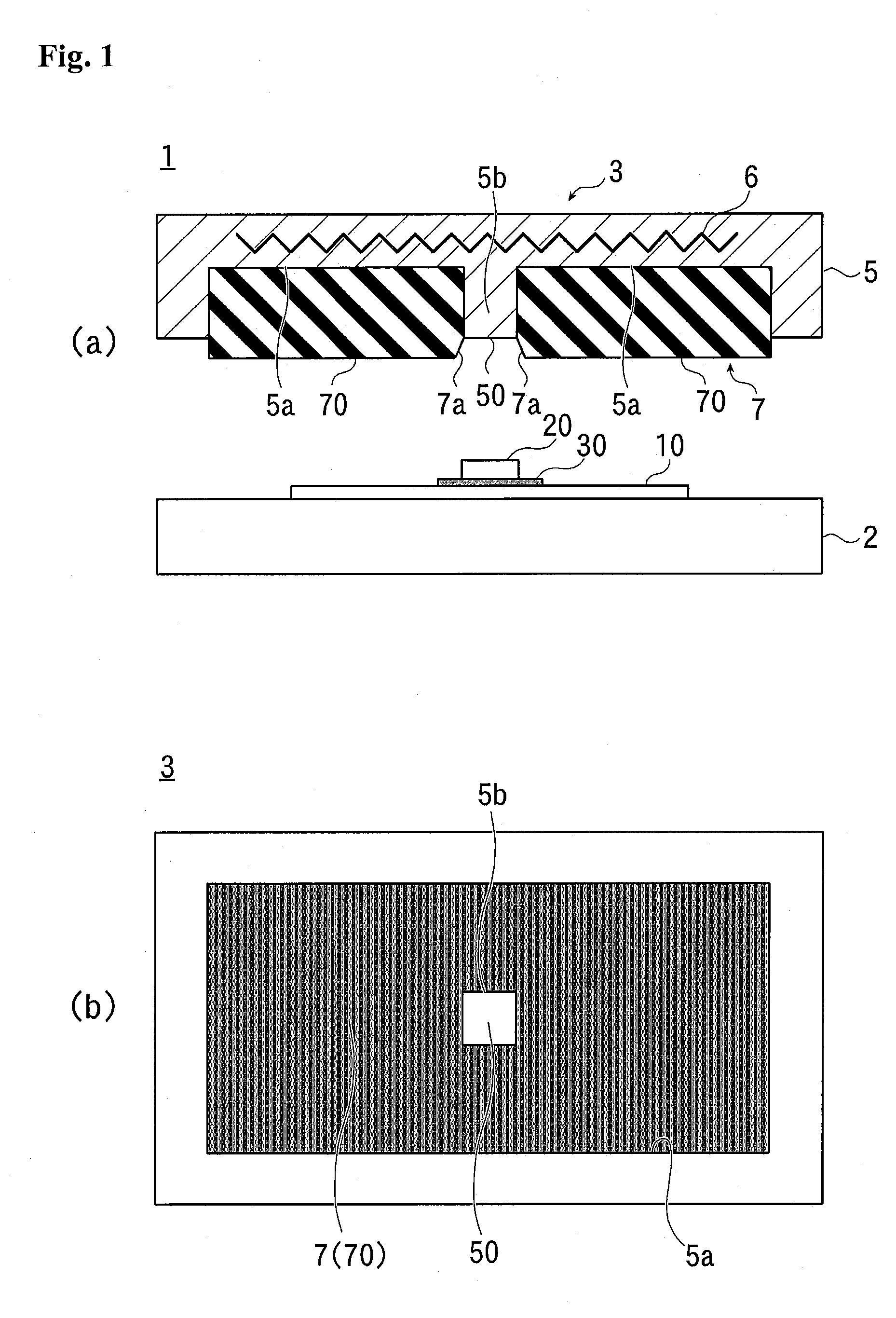
[0040]FIG. 1 (a) illustrates the mounting device according to the embodiment in a schematic partial cross-sectional view, and FIG. 1 (b) illustrates a pressing side of the thermocompression bonding head in the mounting device in a schematic diagram.

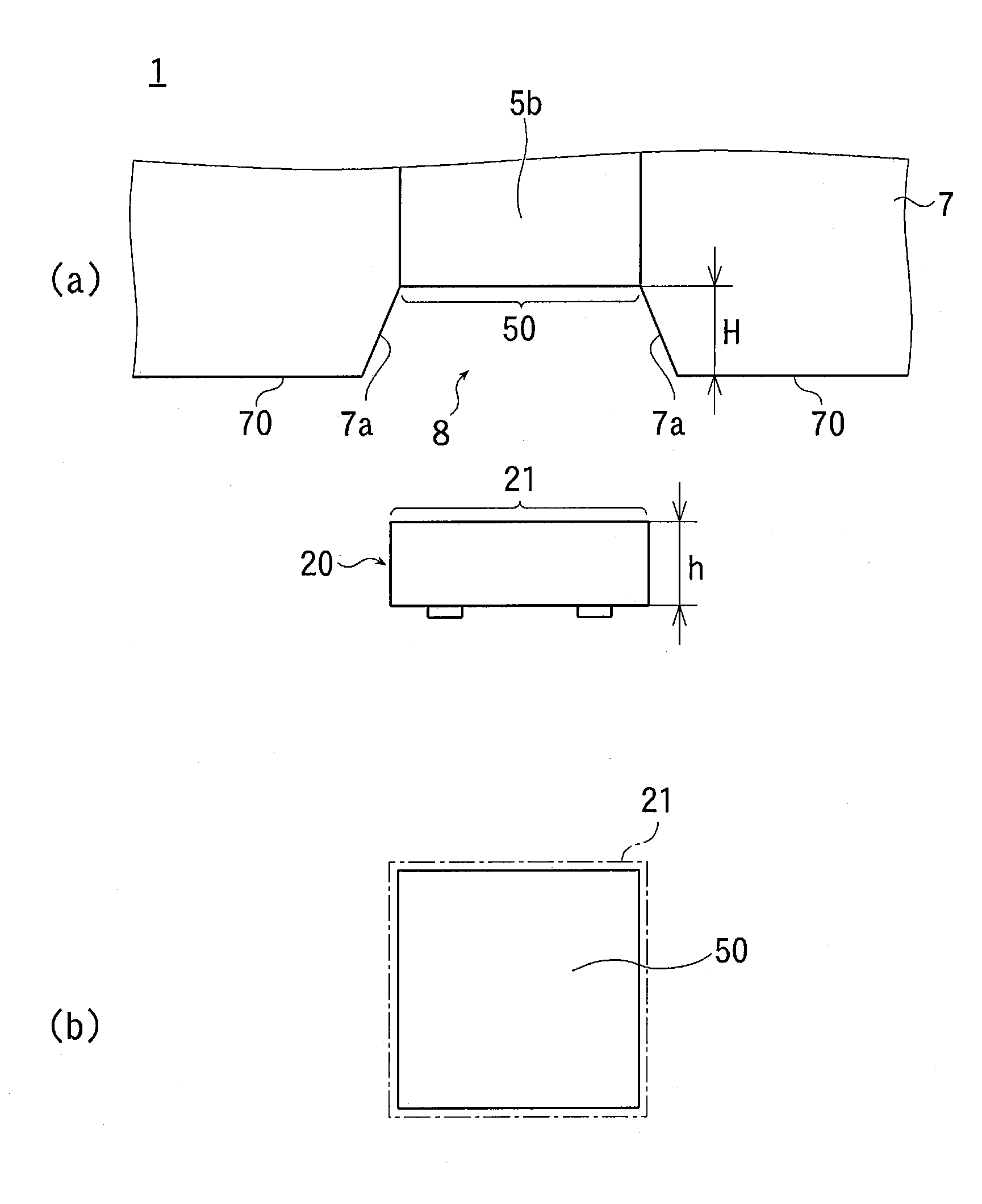
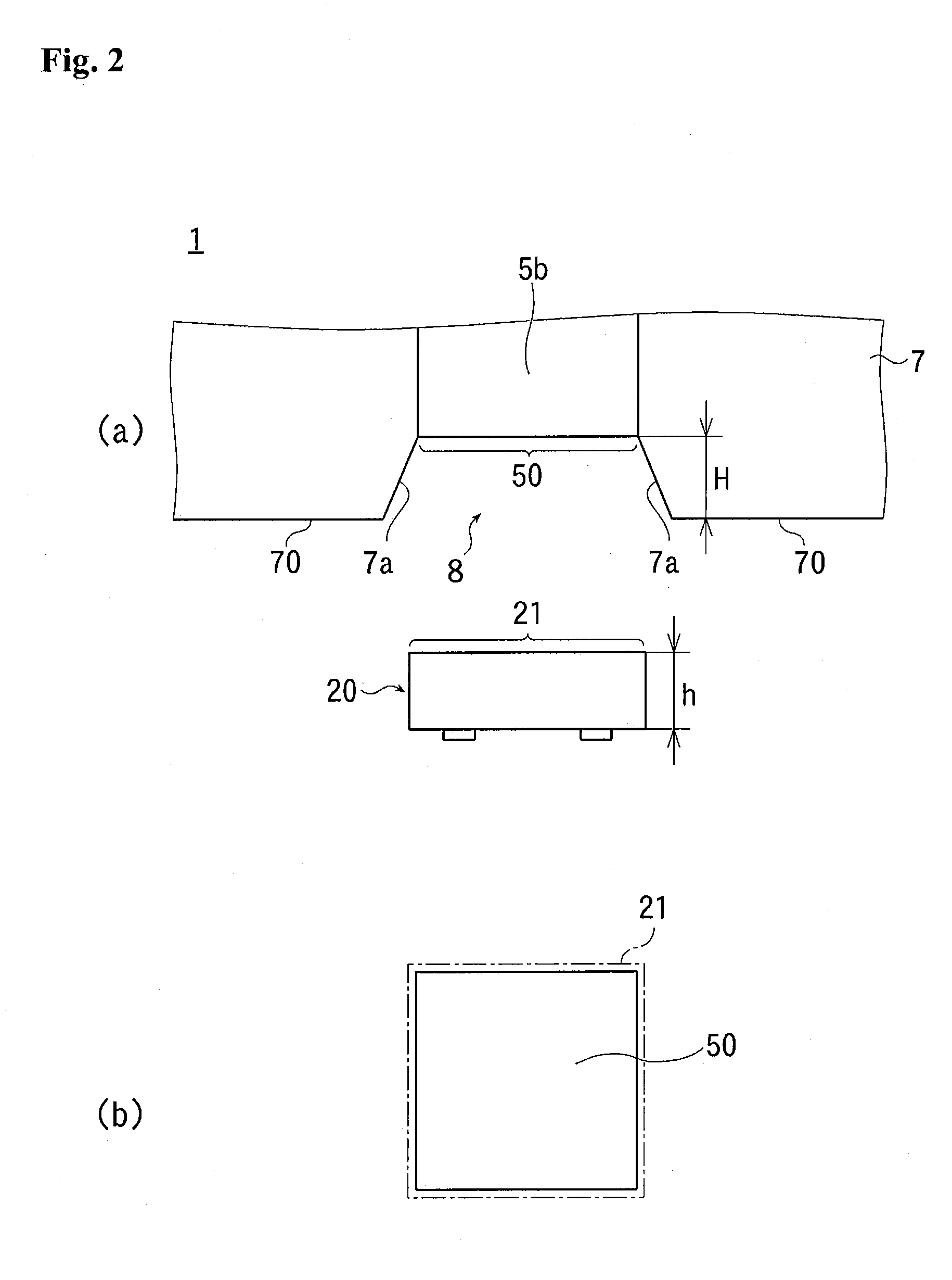
[0041]FIGS. 2 (a) and (b) illustrate a measurement relationship between a pressing surface of the thermocompression bonding head and a top region of an electric component in schematic diagrams.

[0042]As illustrated in FIGS. 1 (a) and (b), a mounting device 1 according to the embodiment includes a base 2 placing thereon a wiring board 10 having a wiring pattern (not shown) and a thermocompression bonding head 3 applying pressure and heat to an electric component 20 serving as a target to be thermally compressed such as an IC chip.

[0043]Herein, ...


PUM

PropertyMeasurementUnit
Thicknessaaaaaaaaaa
Pressureaaaaaaaaaa
Sizeaaaaaaaaaa

Abstract

The present invention provides a thermocompression bonding head capable of mounting an electric component on a wiring board in a short time with high connection reliability, and provides a mounting device using the same. A thermocompression bonding head 3 includes a heatable metal head body 5 having an elastic pressure-bonding member 7 made of elastomer and a metal pressing member 5b. The metal pressing member 5b, corresponding to an electric component 20 as a target to be bonded with pressure, is provided as a united body with the head body 5, and the elastic pressure-bonding member 7 is attached to the head body 5 such that a pressing surface 50 of the metal pressing member 5b is exposed in a recessed state on the periphery of the metal pressing member 5b. The head body 5 is made of a frame-shaped member having a concave portion 5a, and the metal pressing member 5b is integrally formed in the concave portion 5a of the head body 5. Further, the elastic pressure-bonding member 7 is housed and attached in the concave portion 5a.

Description

TECHNICAL FIELD[0001]The present invention relates to a technology for mounting a variety of electric components. More particularly, the present invention relates to a thermocompression bonding head for mounting an electric component using an adhesive agent and to a mounting device using the same.BACKGROUND ART[0002]Generally, in a case where a passive component such as a resistor and a capacitor is mounted on a wiring board, solder serving as a connecting material is melted in a reflow furnace so as to mount the passive component.[0003]On the other hand, in a case where an electric component such as an IC chip is mounted on a wiring board, the electric component is packaged and mounted by solder, or the IC chip is directly placed on the wiring board and mounted by wire bonding or flip chip.[0004]In a case where such an electric component is mounted by the flip chip using a conductive adhesive agent and the like, a hard pressure-bonding head made of metal and / or ceramic and the like...

Claims


Application Information

Patent Timeline
IPC IPC(8): B30B15/34
CPCB30B5/02B30B15/024H01L2924/07802H01L2924/07811H01L2924/01075H01L2924/01006H01L24/16H01L24/32H01L24/73H01L24/75H01L24/81H01L24/83H01L2224/16225H01L2224/32225H01L2224/73204H01L2224/75282H01L2224/75303H01L2224/75315H01L2224/81903H01L2224/83203H01L2924/01004H01L2924/01033H01L2924/14H01L2924/19041H01L2924/19043H01L2924/01005H01L2924/00H01L21/52
Inventor FURUTA, KAZUTAKATANIGUCHI, MASAKI
Owner DEXERIALS CORP
Learn More