Connection structure of terminal fitting and connection method of terminal fitting

Active Publication Date: 2017-07-13
YAZAKI CORP
View PDF1 Cites 3 Cited by
  • Summary
  • Abstract
  • Description
  • Claims
  • Application Information

AI Technical Summary

Benefits of technology

The present invention aims to provide a connection structure and method for a terminal fitting that can collectively connect multiple electric wires with high reliability, while minimizing weight and space requirements. The technical effects of this invention include improved connection reliability, weight and space savings, and the ability to connect multiple wires at once.

Problems solved by technology

However, in the case of the above-mentioned structure in which the terminal fittings are stacked and fastened with the bolt, the terminal fittings connected to the respective grounding wires are stacked and fastened with the bolt, the weight of the terminal fittings increases as the number of the grounding wires increases.
Furthermore, the thickness of the stacked terminal fittings increases as the number of the grounding wires increases, whereby a large space for accommodating the terminal fittings is required to be secured above the grounding face.
Moreover, since fastening work is performed after bolt / nut length adjustment associated with the stacking of the terminal fittings has been completed, the work takes time.
However, in the case of this joint connector, since holding mechanisms (for example, engaging lances) for holding the connection terminals are required to be provided inside the housing, it is difficult to make the housing small in size.
Furthermore, since the housing equipped with the holding mechanisms is required, it is inevitable that the cost of the joint connector will increase.
Still further, in the case of the fastening using the bolt, the bolt may become loose, and the connection reliability after the connection may be degraded in some cases.
However, the relative postures of the connection terminals become unstable when the connection terminals are crimped with a crimping machine and there is a danger of causing fluctuations in crimping strength.

Method used


Image

  • Connection structure of terminal fitting and connection method of terminal fitting
  • Connection structure of terminal fitting and connection method of terminal fitting
  • Connection structure of terminal fitting and connection method of terminal fitting

Examples


first embodiment

[0039]First, a connection structure and a connection method of a terminal fitting according to a first embodiment of the present invention will be described.

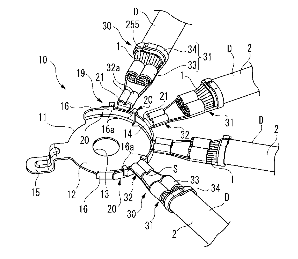
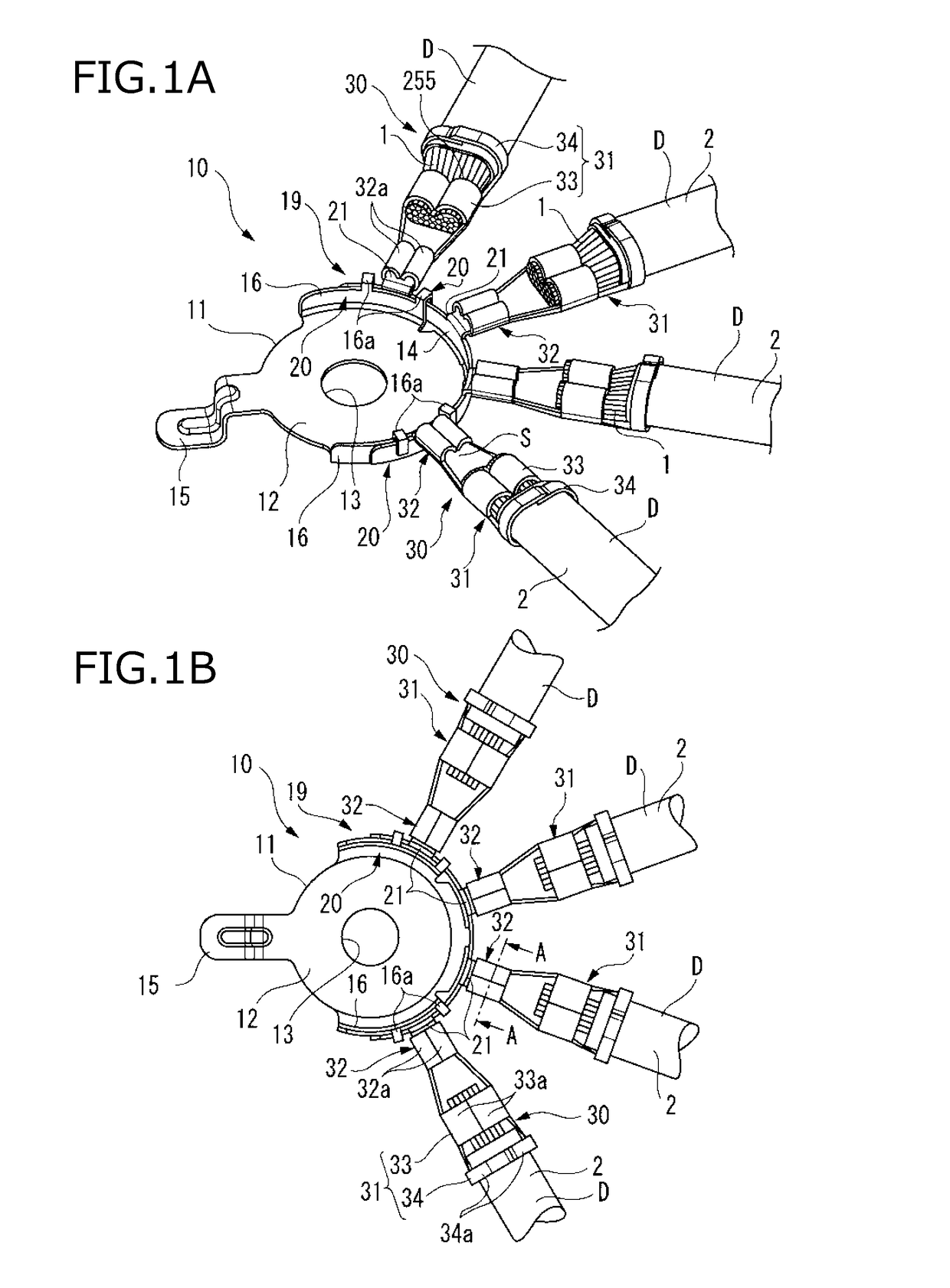
[0040]FIGS. 1A and 1B are views illustrating the connection structure of the terminal fitting according to the first embodiment; FIG. 1A is a perspective view showing a terminal fitting 10 to which grounding wires D are connected, and FIG. 1B is a plan view showing the terminal fitting 10 to which the grounding wires D are connected.

[0041]As shown in FIGS. 1A and 1B, in the connection structure of the terminal fitting according to the first embodiment, the terminal connection parts 21 of the terminal fitting 10 are connected to connection terminals 30. The terminal fitting 10 is conducted and connected to a grounding face, such as a vehicle body. The connection terminals 30 connected to the terminal fitting 10 are provided at the end sections of the grounding wires (electric wires) D of vehicle-mounted circuits (auxiliary device...

second embodiment

[0086]Next, the connection structure of a terminal fitting according to a second embodiment of the present invention will be described.

[0087]Since the components other than the terminal connection parts of the terminal fitting are almost the same in structure as those according to the first embodiment, they are designated by the same reference numerals and signs, and their descriptions are omitted.

[0088]FIGS. 9A and 9B are views showing states in which the caulking pieces 32a of the fastening connection section 32 are fastened to the terminal connection part 21A of the terminal fitting according to the second embodiment of the present invention; FIG. 9A is a cross-sectional view before the fastening of the caulking pieces 32a, and FIG. 9B is a cross-sectional view after the fastening of the caulking pieces 32a.

[0089]As shown in FIG. 9A, the terminal connection part 21A of the terminal fitting 10 according to the second embodiment has the engaging walls 22 protruding to the upper fa...

third embodiment

[0104]Next, a connection structure of a terminal fitting according to a third embodiment of the present invention will be described.

[0105]Since the components other than the terminal fitting are almost the same in structure as those according to the first embodiment, they are designated by the same reference numerals and signs, and their descriptions are omitted.

[0106]FIGS. 10A and 10B are views illustrating the connection structure of the terminal fitting according to the third embodiment; FIG. 10A is a perspective view showing a terminal fitting 110 to which the grounding wires D are connected, and FIG. 10B is a plan view showing the terminal fitting to which the grounding wires D are connected. FIGS. 11A and 11B are views showing the connection structure of the terminal fitting according to the third embodiment; FIG. 11A is a perspective view showing the terminal fitting and the connection terminal, and FIG. 11B is a plan view showing the terminal fitting and the connection termi...


PUM


Abstract

A terminal fitting includes a terminal body and terminal connection parts extended from the terminal body. Connection terminals each has a pair of caulking pieces, and each of the connection terminals configured to be connected to an end part of an electric wire. In each of the terminal connection parts, the connection terminal is caulked to the terminal connection part so that the pair of caulking pieces enfold outsides of a pair of caulked pieces provided on the terminal connection part in a state that a bottom face between the pair of caulking pieces faces an opening between ends portions of the pair of caulked pieces. The terminal fitting is connected to the electric wires through the connection terminals.

Description

CROSS REFERENCE TO RELATED APPLICATION[0001]This application is based on Japanese Patent Application (No. 2016-001673) filed on Jan. 7, 2016, the contents of which are incorporated herein by reference. Also, all the references cited herein are incorporated as a whole.BACKGROUND[0002]1. Technical Field[0003]The present invention relates to a connection structure and a connection method of a terminal fitting.[0004]2. Background Art[0005]A connection structure is known in which the connection plates of a plurality of terminal fittings to which a plurality of grounding wires is connected are stacked mutually, a common bolt is inserted into mounting holes provided in the connection plates, and the bolt is fastened to a grounding face (for example, a predetermined position of a vehicle body), whereby the plurality of grounding wires is collectively conducted to the grounding face via the stacked terminal fittings (for example, refer to JP-A-2012-190749).[0006]However, in the case of the a...

Claims


Application Information

Patent Timeline
IPC IPC(8): H01R13/74H01R43/048H01R4/18
CPCH01R13/748H01R4/185H01R43/048H01R4/188H01R4/18H01R11/09H01R11/12Y10S439/907H01R11/32H01R13/2428
Inventor YAMAMOTO, TAKATATSUNAGANISHI, YUKINARI
Owner YAZAKI CORP
Why Eureka
Try Eureka